(E16) Capacitance
An electrically charged object--an insulator or an insulated conductor--can ordinarily hold only a small amount of electric charge. Adding more charge quickly causes the voltage to rise--and since the object can usually receive charge only from a higher voltage, it becomes increasingly harder to add much more. However, after 1745, in the Dutch city of Leyden, a neat way for storing much more of it was found by E.G. von Kleist and Petrus Van Musschebroek. Kleist and Musschenbroek tried to see if water could be charged electrically. They placed the water in a cylindrical glass jar with a metal rod emerging from it to transmit the charge (the ball-shaped end, common in apparatus dealing with static electricity, reduces leakage). The water could indeed be charged, thanks to the insulating properties of the glass. But something else was noted: the device, when held in the experimenter's hand, could hold much more electric charge--enough to give a surprising shock, or produce visible sparks. 
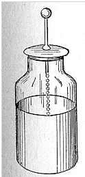
Further experiments showed that the water could be replaced by metal foil lining the inside of the jar (chemically depositing thin metal on glass was familiar from the manufacture of mirrors). The hand holding the outside of the jar, which enabled more charge to be stored, could also be replaced by foil covering the outside, separated from the one inside. The final form of the "Leyden jar" (as it became known) was thus a glass container lined with foil inside and out, and with a metal rod rising from its inside, connected to the inner foil (say, by a short chain, as in the drawing below).
The Leyden jar was the earliest example of an electric capacitor. ("Condenser" or "Kondensator", to some people.)
Capacitors will never displace storage batteries: the amount of electric energy they can store is still much, much less. Their advantage is that they can deliver their energy very quickly--in a flash, you might say. In fact, one of their uses is powering electronic flash units in photography. In such a unit a capacitor is discharged through the circuit of a special lamp, producing a short but intense flash of light. Another application is in the conversion of AC to DC (alternating current to direct current). House wiring uses AC, whose voltage changes in an up-and-down cycle 60 times per second.That is fine for lighting or for AC motors, but most electronic devices--radios, TVs, computers etc.--need a steady unchanging voltage. How does once convert AC to DC?
Devices exist, so-called solid-state rectifiers (or diodes) which only allow current to flow in one direction (earlier, vacuum tube diodes were used, based on the "Edison effect"). They offer a very low resistance to current in one direction, and a very high one in the opposite direction. Denoting them by the customary symbol of a triangle on a flat base, and defining the direction of the electrical current as (+) to (-) say
Flow towards the triangle (+ to –) 10,000,000 ohm (drawing) 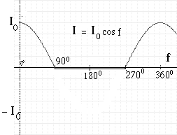
Since half the wavelength (the part in the graph where I should become negative) is blocked, the wave now consists of one-sided "teeth." That may not matter when one charges a storage battery, but a radio, for instance, needs a smooth voltage; one that is interrupted 60 times each second will, at the very least, emit a 60-cycle hum. Each cycle of the output current consists of two parts. For 1/120 second (the "tooth" in the rectified current) electric current flows easily through, though its voltage rises and falls. Then for the next 1/120 second ("the gap") no voltage is provided at all. A capacitor can help by storing up electric charge during the first part and then releasing it during the second, to bridge the gap.
Now suppose the voltage source is not a battery but an alternating voltage--especially, one with frequency much higher than 60 cycles, e.g. a radio signal, or the voltage which drives a loudspeaker when music is played. Now the voltage on one plate will constantly go up and down, and since the other plate tries to follow, a constant AC current will circulate, charging and discharging the capacitor plates. In other words--a capacitor will transmit alternating current (AC) but will block DC. It is not a "short circuit" allowing all AC to pass, but offers a sort of resistance (the name is "impedance") which limits its AC current, just as resistance limits currents of any kind, and it also shifts the peak of the wave. The higher the frequency, the smaller the impedance, which means, the more easily does the AC current flow across the capacitor. Unlike flow through a resistance, here no electric energy is lost and there is no heating. As described above, the power supplies inside a TV, computer, radio etc therefore may have at their input a rectifier followed by large capacitor. There may still be a ripple left as the voltage drops a bit between the "teeth" of the rectified wave, and additional filters smooth it away (if your radio hums loudly, something is wrong with the DC power supply--maybe the capacitor leaks). More complex circuits rectify both sides of the AC wave.
Where it is useful: Suppose you have an amplifier with several stages--the first stage amplifies the signal 5 or 10 times, the second one does so again, until a weak signal produced (say) by a microphone has enough energy to drive a big loudspeaker. Each stage is a separate circuit, with transistors and other elements, powered by some fixed constant DC voltage. The voltages at any point of the circuit--in particular, the input and output points--is therefore the sum of two parts. First, there is a constant voltage, defined (in the simplest case) by Ohm's law and by the resistances feeding current into the point and out of it. And second, added to this is the signal, a rapidly varying voltage, tracking (in this example) the pressure on the microphone from the sound being amplified. When the output voltage of one stage is to be transmitted to the next, we want to pass along the signal, but not the constant part, which would affect the operating point of the next stage. How can one separate the two? Simple! Insert a capacitor in the connection that carries the output to the next stage: the signal passes through, the direct voltage does not. Where it is a nuisance: Have you ever experienced crosstalk on a telephone? As you speak to the party at the other end, some unrelated conversation is added to the sound, interfering with your connection. The reason may be that wires of different telephone circuits run along each other, and the capacitance between them is large enough to transmit an echo of its own conversation to its neighbor. (Fiber optic signal transmission by laser light is rapidly eliminating this nuisance.) To prevent such "signal pick-up" between different sections of a computer or a TV receiver, they are often enclosed in grounded metal boxes, which don't let the signal through. "Touch pads" which trigger a device when you place your finger on them, work through the extra capacitance between them and your finger, which unbalances a delicate circuit. Some metal detectors use a similar principle. In the era of vacuum tubes, circuits included large components, including the tubes themselves. Capacitance between large objects is also larger, so unwanted "stray capacitance" (e.g. between parts of the vacuum tube) hampered operation at high frequencies. Today's computers, using etched silicone chips, work at much, much greater speed, because the dimensions of circuit components are very small, greatly reducing stray capacitances between different parts. Tidbit In the middle 1800s the idea arose of connecting the US and Europe with an insulated undersea cable, to send telegraph messages from one continent to the other. When those enormous cables were finally laid (overcoming great technical difficulties), it turned out that messages could only be sent very slowly. A signal sent as a crisp on-off dot or dash of the Morse code would arrived in the shape of a spread out "sandhill." But of course! The cable and the ocean around it together formed a giant capacitor, and every time a signal was sent, it took some time to charge and to discharge (see http://en.wikipedia.org/wiki/Submarine_communications_cable#Bandwidth_problems )
A Scottish scientist at the University of Glasgow, William Thomson, found a way to speed up operations and was well rewarded for it--also, he was honored as Lord Kelvin (after a stream in Glasgow) and after his work on heat, his title became associated with the absolute scale of temperature. Modern cables also include "repeater amplifiers" along their length.
|
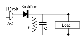 The simplest circuit of this sort is pictured on the right below, using the usual notation of circuit diagrams for a capacitor--two equal parallel lines, symbolic of the two parallel plates (or foils) of a capacitor [to denote an electrolytic capacitor, one line is curved]. A rectangle stands for the load which uses the current--radio, music player, or whatever--and the AC source is drawn as a power plug. The bottom line is supposed to be connected to the grounded side of the plug. Such wiring may exist in cheap devices completely enclosed in plastic and no chance of the interior being touched; otherwise an isolating transformer is needed, discussed further below.)
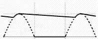 On the left is the graph of input voltage (broken line) and of the output voltage. The peak output voltage is where the capacitor soaks up the peak of the cycle, and the voltage gap is bridged by the electric charge stored in the capacitor. This is the very simplest DC supply; note its output still contains a ripple. More sophisticated circuits filter out the ripple to a smooth output. One simple way is to place a battery across the output terminals. The charging current of the battery rises and falls with the cycle of the rectifier, but the output voltage is essentially that of the battery.
Cars often use this trick, with electric power generated as AC by an "alternator" connected to the engine.
On the left is the graph of input voltage (broken line) and of the output voltage. The peak output voltage is where the capacitor soaks up the peak of the cycle, and the voltage gap is bridged by the electric charge stored in the capacitor. This is the very simplest DC supply; note its output still contains a ripple. More sophisticated circuits filter out the ripple to a smooth output. One simple way is to place a battery across the output terminals. The charging current of the battery rises and falls with the cycle of the rectifier, but the output voltage is essentially that of the battery.
Cars often use this trick, with electric power generated as AC by an "alternator" connected to the engine.