(E-5) Resistor Networks: Using Ohm's Law
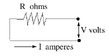
Many loads act as resistors--the glowing wires in toasters or ovens, or the glowing filaments in "incandescant' lamp bulbs. Other loads can often be approximately handled as resistors--e.g. fans in an AC circuit, even though they may affect the voltage wave. Here only the simplest circuits will be studied, those involving resistors and steady currents (either DC or AC). The currents in any of them can be derived from Ohm's law
This holds across any portion of the circuit: if V is the voltage drop across it and R its effective resistance, then I is the current flowing in it. Of course, at a node in the circuit where several conductors meet, the sum of the currents flowing into the note must always equal the sum flowing out. 
By common convention, a resistor (with no other electrical properties) is indicated by a zig-zag line, with the value of the resistance indicated by
Ω , the capital Greek letter omega. (kilo-ohms or thousands of ohms are indicated by kΩ, mega-ohms or millions of ohms by MΩ ; the larger the resistance, the less current is allowed to trickle through it!)
In the diagram above, suppose the resistance is R=12Ω and when the switch is closed, the voltage at the right end of the resistor is V=9 volt. The other side of the resistor is grounded and the current is therefore 
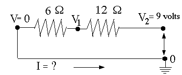
Suppose the circuit contains two resistors connected end-to-end or "in series", to that the same current I passes both (resistors "in series" were already met earlier, on a more casual level). Let as before the right end be connected to V2, the left end grounded and the voltage at the intermediate point be denoted V1. If the resistors are of 12 Ω and of 6Ω, Ohm's law must be satisfied in each segment, so An extra equation, but also an extra unknown variable, V1 (we are given V2 = 9 volt). Using the fact that the current I flowing into the node in the middle equals the current I flowing out of it, this can be reduced to one equation
divide by 3 and exchange sides: V1 = 3 volt The current can be calculated from either equation (both should give the same result), e.g. The current is smaller than before, because an additional resistance was inserted. Notice that two resistors 12Ω and 6Ω in series act like a single resistor of (12+6)=18Ω 
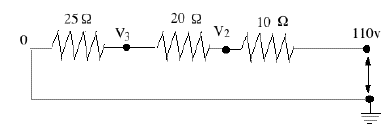
Another example, with an AC source and 3 resistors in series, is shown above. In an AC circuit, the voltage constantly changes and reverses polarity, and the value of 110 volt is really some sort of average (implying that 110V DC would deliver just as much energy). But because simple resistors handle DC and AC the same way, we may just as well pretend we have 110V DC. If I is the current, V1 = 110 volt, and (V2, V3) the intermediate voltages (the right end is at zero as before),then (1) I = (110 – V2)/10 or 10 I = 110 – V2(2) I = (V2 – V3)/20 or 20 I = V2 – V3 (3) I = (V3)/25 or 25 I = V3 Add them together A Voltage DividerA voltage divider is typically a thin wire with appreciable resistance wound around a long tube (straight or curved), with a movable contact in the middle. See diagram:
Rotating control knobs on a radio or another instrument are likely to be connected to voltage dividers. The sliding contact C (arrowhead) can tap any voltage between V (when it touches A) and zero (when it touches B), and accordingly adjust the loudness of the sound, the brightness of the display or some other output. Often the sliding contact goes to the input of an amplifier, so that it draws only a small current and does not create an appreciable variation of the energy demand. If only A and C are connected, this becomes a variable resistor, but then the power drawn varies widely with the setting. Variable resistors are marked in circuit diagrams by a zig-sag line for the resistor, crossed diagonally by an arrow. Resistors are important elements in many devices. In a radio, currents are small and do not generate much heating, so resistors are often small plastic cylinders from whose ends connecting wires stick out. The resistor element is very much like the lead of a pencil, which conducts electricity by containing graphite, a form of carbon. Here the carbon may be finely mixed with a non-conducting substance, to control resistivity, or a conducting layer is deposited on the core.
"Wire wound" resistors have a special wire wound around a ceramic tube, covered with insulating glaze. They tend to be more stable and can take more heating, i.e. larger currents.
|
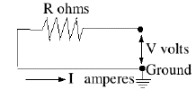
 Notice that only voltage difference counts. In the above formulas, V really means "the voltage difference between the ends of the resistor." Put differently, the value assigned to the voltage (or "electric potential") at any point is generally only defined relative to other points. The ambiguity can be removed by choosing--for the purpose of calculations--one point to have voltage zero. In practical circuits, this is usually a point connected to the ground which, though not always as good a conductor as metal, is large enough to maintain a constant voltage that can serve as reference. In diagrams the ground is marked by a number of short horizontal lines, whose length decreases towards bottom so that they fill the space of a triangle.