(E14) Early History of Electricity and Magnetism
So far this study has examined the flow of the "electric fluid," stressing aspects relevant to everyday life. But long before people knew of electrons and protons, they wondered--what did such a fluid consist of? A flow through a pipe usually consists of water, compressed air, hydraulic fluid, blood or some other fluid. What kind of material flows in an electric current? They named it electric charge. When it is not flowing, we call it "static electricity" (static = not flowing). 
Static electricity was already known to ancient Greek philosophers. Thales of Miletus, around 600 BC, probably knew that amber--fossilized pine-sap, a plastic-like non-conducting material--could attract light pieces of straw and feather when lightly rubbed with dry cloth or fur (most modern plastics also act that way--a plastic comb, for instance). Before discussing this further, however, it may help to examine permanent magnets, which Thales also knew and which share many of the features of static electricity.
Around the year 1000 (or earlier, according to some sources) the Chinese discovered another strange (but very useful!) property of magnets. Placed in a vessel floating in a bowl of water, a lodestone or a magnetized steel bar always lined up with its magnetic poles--the points where the magnetic pull was strongest--in the north-south direction. From that grew the magnetic compass, which helped sailors keep a straight course far from land and made possible voyages of discovery such as the ones by Columbus. The study of nature by Greek philosophers (about 500 BC-200 AD) was followed by an era of little progress. Science again started advancing after the invention of the printing press by Johann Gutenberg (d. 1468), with the new astronomy of Nicolaus Copernicus (1473-1543), Galileo Galilei (1564-1642) and Johannes Kepler (1571-1630). The era of new ideas, art and instruments which followed became known as the renaissance, French for "rebirth."
One signpost of the new era was the book "De Magnete" (Latin for "On the Magnet") published in London in 1600 by William Gilbert, a prominent medical doctor and (after 1601) personal physician to Queen Elizabeth I. Gilbert's great interest was in magnets and the strange directional properties of the compass needle, always pointing close to north-south. He correctly traced the reason to the globe of the Earth being itself a giant magnet, and demonstrated his explanation by moving a small compass over the surface of a lodestone trimmed to a sphere (or supplemented to spherical shape by iron attachments?)--a scale model he named "terrella" or "little Earth," on which he was able to duplicate all the directional properties of the compass. (here and (here)
If one cut a bar magnet in half, one might naively expect one half to contain the N pole and the other the S pole, but this never happens. Instead new poles appear at the break, leaving one with two shorter bar magnets, each with a matched pair of (N,S) poles. (Figure)
Also, the new poles are weaker. Gilbert correctly explained this observation by proposing that the sources of the magnetic force were distributed all over the substance of the magnet. The poles at the end were merely the points where that force emerged to the outside world. Each half of the broken magnet had such points, but since each pole channeled its force from only half as much magnetized material, that force was weaker.
If each magnet had two matched poles, why could one magnet attract another? Because the distances between the poles usually differ. 
Suppose we place an iron bar (thin outline) next to a magnet with poles marked N and S (drawing). It now becomes a temporary magnet, with poles N' and S' of equal strength. Then the neighboring poles S and N' attract each other strongly, while the pairs (N, N') and (S, S'), being much further apart, repel each other much more weakly, not enough to overcome the strong attraction.
At great distances the forces are nearly equal, and the tendency is to rotate the magnet (as happens with a compass needle) rather than pull it closer.
Gilbert studied the strange force, finding (for instance) that while a thin layer of water disrupted electric phenomena, a thin layer of oil did not. He even constructed a "versorium," a lightweight nonmetallic pivoted needle resembling a magnetic compass, which obviously inspired it. Near an electrified object that needle would point in the direction of the "electrick force"--in what today would be called the direction of the electric field. However, he did not realize that just as two varieties of magnetic poles existed, N and S, so electricity also came in two types, now denoted + and – (positive and negative electric charges). That was only found around 1733 by Charles Dufay in France, and like magnetic poles, charges of different types attracted each other and of the same type repelled.
One big difference existed, however: positive and negative charges could be separated. While every magnet carries N and S poles of equal strength, electrified objects could also carry one type of charge only. Rubbing glass created one type, rubbing amber the other. Still, the total charge was always conserved, so if glass rubbed with cloth became positively charged, the cloth itself always received an equally large negative charge.
Matter contains atomic-size electric charges, which we now know as electrons (negative) and atomic nuclei (positive, since they contain positive protons). In the straw, as in any other ordinary material, these are thoroughly mixed, so that any bit of matter contain equal amounts of positive and negative charge. As a result, it behaves as an uncharged object.
In passing one may note that some materials--e.g. very good insulators like teflon, charged deep in their interiors--can keep + and – charges separated for a long time without external intervention. They are therefore the electrical equivalents of permanent magnets and are accordingly named "electrets." Electrets are nowadays used in high-performance microphones.
The first group of substances, the ones who do not allow charge to move, are known as (electric) insulators. Today many more such materials are known, such as rubber, motor oil, glass and practically all plastics, e.g. polyethylene and nylon (polyester). Nylon shirts tumbled in the hot dry air stream of a clothes dryer tend to charge electrically by friction and to cling together, whereas cotton shirts do not.
On the other hand metals, carbon and watery solutions (especially the ones that contain dissolved electrolytes such as salt) freely allow electric charge to flow from point to point and distribute itself among all the locations it can reach. Such materials are called electric conductors. If we try to charge a metal rod held in one's fingers, the charge will spread to the fingers to the body, and from there, perhaps, through the leather soles of one's shoes to the ground and to the rest of the world. No observable charge remains on the rod, so any observation will conclude that it has "drained away." However, such a rod can be charged if we insulate it from our fingers with a piece of polyethylene sheet.
(E15) Static ElectricityGroundingThe process of providing a conduction path through which static electricity can escape to the ground (which has enough bulk and humidity to conduct it away) is known as grounding. (It was already mentioned earlier, as one way of increasing the safety of home wiring.) If you work with computer chips (tiny electric circuits and components, etched on silicon) you should always take care to ground your body, e.g. by first touching a grounded object (say, the wall of the room or some big metal object), before moving from your chair. For your body might carry a static electric charge--developed, say, by friction of your shirt or blouse--and when you touch the chip, some of it may jump over and damage the delicate circuitry ("zap" or "fry" the chip). The risk is particularly high in modern offices, where even in the summer air is kept dry by air conditioning, where the floor is paved with insulating tiles and the workers are likely to wear shoes with rubber soles. The amount of static charge produced by friction is very, very small--compared to, say, the charge transmitted each second by 1/1000 of an ampere ("one milliampere"). That is why even a thin layer of moisture on one's hand can discharge it. In grounding electric circuits in the home, on the other hand, a substantial copper wire is needed. Copper is the preferred conductor in commercial applications, in the wiring of homes and vehicles, and in motors. Silver is a better conductor, and gold is better still, which is why it is used (as a coating, in tiny quantities) in some precision microcircuits. Weight for weight, aluminum beats out copper, too, but (as already noted) it is rarely used in wiring, because it reacts chemically with the oxygen in air to produce a thin insulating surface layer, whose high resistance can cause local heating and even start a fire.
The US treasury was not exactly enthusiastic to help, but it consented, and tons of silver were converted to insulated electrical wiring. The silver was returned to the treasury after the war and according to the story, everything was accounted for. 
Like the electrically polarized straw in the preceding section, a metal rod on an insulating stand will also be "polarized" by a charged object held near one end. Suppose the charged object, as before, is positive, so that negative charge is drawn to the end nearest to it. With a wire, we can now drain the positive charge from the other end (drawing). If that wire is disconnected while the charged object is still in place, the metal rod remains with a net negative charge, and will stay negatively charged even after the original positive charge which caused the polarization is removed. In demonstrations of static electricity, metal objects are often charged this way.
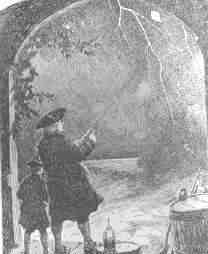
Suspecting that lightning was an electrical phenomenon, Franklin in a famous experiment flew a kite beneath a thunderstorm and extracted elecrical sparks from a key hanging from the end of the kite string (some critics have claimed he described the experiment without actually performing it). Even though Franklin claimed he carefully separated himself from the kite--standing in the dry area beneath an overhang, with a dry insulating string between him and the wet kite string--it was a foolhardy thing to do. G. Richman, a Russian scientist in St. Petersburg, tried to repeat the experiment shortly afterwards and was killed when a stroke of lightning came down the line. Today scientists at the Langmuir Lightning Laboratory in New Mexico bring lightning to their instruments from overhead thunderstorms by launching into them small rockets trailing thin metal wires. A lightning rod is a vertical metal rod rising above the highest point of a building, connected to a stake in the ground (or a substantial water pipe) by a thick copper wire held by posts outside the walls. If lightning strikes the rod, the electric charge is channeled safely to the ground, without passing through the building where it might endanger lives, start a fire or destroy equipment. The electric charge of lightning is apparently created by friction of frozen raindrops (like hailstones) blown upwards by updrafts in thunderclouds, encountering other such hailstones falling back down. More is given at the end of the section on the Van de Graaff voltage generator.
Lightning does occasionally hit power lines, causing short spikes of high voltage, which can destroy computer chips. Computers and other electronic devices are therefore often protected by special attachments of "nonlinear" materials which deviate markedly from Ohm's law. With low voltages, they draw a negligible electric current, but they give way to sudden high voltage pulses and divert them safely before they cause damage. That protection is in addition to the one by circuit breakers, which might not react quickly enough.
Ben Franklin supported the "two fluid" explanation, and today we tend to agree, having observed electrons and nuclei, atomic carriers of (–) and (+) charge. However, he also chose the naming of positive and negative electricity. Much later it was realized that reversing the choice would have made more sense, because most common electric phenomena, e.g. conduction of electricity in metals, involve the motion of electrons, carrying what Franklin named a negative charge. By then, however, it was much too late to change the convention.
Coulomb Measures Electric Charge (Optional, but note the formula)
It was Newton who first discovered around 1680 that the observed motion of planets and their moons could be precisely calculated from some fundamental laws of motion and gravity. About a century later a French military engineer, Charles Augustine Coulomb, made it possible to calculate and predict the motion of electric charges in a similar manner. It is therefore only fair that the unit of charge is named "coulomb" in his honor. Military engineers in 18th century France (and later) were well trained in science and made many important contributions to it. In his official capacity Coulomb supervised the building of fortifications on the Caribbean island of Martinique, and later in France the construction and maintenance of canals, ports and of the royal waterworks which fed the exquisite gardens of Versailles. He also conducted scientific studies of sliding friction, discovering that besides depending on the nature sliding surfaces, it was approximately proportional to the force holding them together, regardless of the contact area--e.g. when a brick-shaped block of wood was dragged along a flat horizontal surface, the force of friction was approximately the same no matter which side it rested on.
By 1773 it was well known that the direction of the compass needle underwent a regular 24-hour cycle, a tiny variation just barely observable even with oversized compass needles. The Paris Academy of Sciences therefore offered a prize for the most sensitive compass instrument, which might perhaps help investigate this phenomenon. The prize was awarded in 1777 and part of it went to
The instrument was adopted in 1780 by the Paris observatory and worked very well, but it was noted that the needle sometimes jumped when the observer touched the eyepiece of the microscope used for observing its tip. Coulomb correctly credited static electric charge on the observer. He had the instrument moved to a basement whose humid air reduced static charging (and whose temperature was less variable), and instructed observers to wait a few minutes near the instrument before touching it, to give any charge on their bodies a chance to leak away. Coulomb's instrument, however, could do much more. It became known as a torsion balance--torsion is the twisting force of a string (here the one of the suspension), which is balanced against some other force. The string hung from a knob which could be turned, and the size of the force could be deduced from the angle be which the string had to be turned to bring the needle back to its first position. Coulomb quickly realized that here was an ideal instrument to measure the feeble force between electric charges. He replaced the magnetic needle with an insulating dry straw, with a small ball of pith (lightweight plant material) at one end, balanced by a paper vane whose air resistance helped the straw stop swinging and settle into equilibrium. A second, identical ball of pith was mounted on an insulating shaft, and lowered next to the first one, at the same distance from the axis of the thread. The ball was then charged with static electricity. By having the balls touch, Coulomb made them share their charge--equally, because they were alike--and the twisting of the knob allowed the force of their repulsion to be measured, at a given distance. Twisting the knob more or less also changed the distance, and in that manner Coulomb could show that like gravity, it varied inversely with the square of the separation distance r -- in other words, it was proportional to 1/r2 . Discharging the fixed ball and sharing the remaining charge by touching, so that each electric charge q was reduced to one-half, Coulomb found that the force dropped to 1/4. That suggested the repulsive force F between two charges q1 and q2 was proportional to the size of each of them. In a formula This formula was the beginning of electricity as an exact science! Coulomb also proved that attraction varied inversely with the square of distance, a more difficult experiment, and that magnetic poles obeyed a similar law. He described his results in 6 reports published in 1785-90. Coulomb's method was adapted by Henry Cavendish in Britain to the laboratory measurement of gravity. That is a much more difficult observation, because the attraction between to spheres is much, much weaker than the electric or magnetic forces measured by Coulomb. Also, because the spheres are massive, the motion of the suspended pair of spheres is quite slow. Nevertheless, by 1796 Cavendish performed that experiment and showed that the pull of gravity between two masses varied like 1/r2, not just between planets and moons (as Newton had shown) but also between masses in the laboratory. Thus all three forces studied--magnetism, electricity and gravity--seemed to display a pleasing symmetry. All three were directed from one center of force to another, and all varied with distance like 1/r2. True, magnetic poles only came in matched pairs, and gravity always attracted, it never repelled. But apart from such differences, nature was remarkably orderly and symmetric.
Or so it seemed up to 1820.
(E16) Capacitance
An electrically charged object--an insulator or an insulated conductor--can ordinarily hold only a small amount of electric charge. Adding more charge quickly causes the voltage to rise--and since the object can usually receive charge only from a higher voltage, it becomes increasingly harder to add much more. However, after 1745, in the Dutch city of Leyden, a neat way for storing much more of it was found by E.G. von Kleist and Petrus Van Musschebroek . Kleist and Musschenbroek tried to see if water could be charged electrically. They placed the water in a cylindrical glass jar with a metal rod emerging from it to transmit the charge (the ball-shaped end, common in apparatus dealing with static electricity, reduces leakage). The water could indeed be charged, thanks to the insulating properties of the glass. But something else was noted: the device, when held in the experimenter's hand, could hold much more electric charge--enough to give a surprising shock, or produce visible sparks. 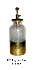
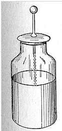
Further experiments showed that the water could be replaced by metal foil lining the inside of the jar (chemically depositing thin metal on glass was familiar from the manufacture of mirrors). The hand holding the outside of the jar, which enabled more charge to be stored, could also be replaced by foil covering the outside, separated from the one inside. The final form of the "Leyden jar" (as it became known) was thus a glass container lined with foil inside and out, and with a metal rod rising from its inside, connected to the inner foil (say, by a short chain, as in the drawing below).
The Leyden jar was the earliest example of an electric capacitor. ("Condenser" or "Kondensator", to some people.)
Capacitors will never displace storage batteries: the amount of electric energy they can store is much, much less. Their advantage is that they can deliver their energy very quickly--in a flash, you might say. In fact, one of their uses is powering electronic flash units in photography. In such a unit a capacitor is discharged through the circuit of a special lamp, producing a short but intense flash of light. Another application is in the conversion of AC to DC (alternating current to direct current). House wiring uses AC, whose voltage changes in an up-and-down cycle 60 times per second.That is fine for lighting or for AC motors, but most electronic devices--radios, TVs, computers etc.--need a steady unchanging voltage. How does once convert AC to DC?
Devices exist, so-called solid-state rectifiers (or diodes) which only allow current to flow in one direction (earlier, vacuum tube diodes were used, based on the "Edison effect"). They offer a very low resistance to current in one direction, and a very high one in the opposite direction. Denoting them by the customary symbol of a triangle on a flat base, and defining the direction of the electrical current as (+) to (-) say
Flow towards the triangle (+ to –) 10,000,000 ohm (drawing) 
Since half the wavelength (the dotted part) is blocked, the wave now consists of one-sided "teeth" (graph). That may not matter when one charges a storage battery, but a radio, for instance, needs a smooth voltage; one that is interrupted 60 times each second will, at the very least, emit a 60-cycle hum. Each cycle of the output current consists of two parts. For 1/120 second (the "tooth" in the rectified current) electric current flows easily through, though its voltage rises and falls. Then for the next 1/120 second ("the gap") no voltage is provided at all. A capacitor can help by storing up electric charge during the first part and then releasing it during the second, to bridge the gap.
Now suppose the voltage source is not a battery but an alternating voltage--especially, one with frequency much higher than 60 cycles, e.g. a radio signal, or the voltage which drives the loudspeaker as music is played. Now the voltage on one plate will constantly go up and down, and since the other plate tries to follow, a constant AC current will circulate, charging and discharging the capacitor plates. In other words--a capacitor will transmit alternating current (AC) but will block DC. It is not a "short circuit" allowing all AC to pass, but offers a sort of resistance (the name is "impedance") which limits its AC current, just as resistance limits currents of any kind, and it also shifts the peak of the wave. The higher the frequency, the smaller the impedance, which means, the more easily does the AC current flow across the capacitor. Unlike flow through a resistance, here electric energy is not lost and there is no heating. As described above, the power supplies inside a TV, computer, radio etc therefore may have at their input a rectifier followed by large capacitor. There may still be a ripple left as the voltage drops a bit between the "teeth" of the rectified wave, and additional filters smooth it away (if your radio hums loudly, something is wrong with the DC power supply--maybe the capacitor leaks). More complex circuits rectify both sides of the AC wave.
Where it is useful: Suppose you have an amplifier with several stages--the first stage amplifies the signal 5 or 10 times, the second one does so again, until a weak signal produced (say) by a microphone has enough energy to drive a big loudspeaker. Each stage is a separate circuit, with transistors and other elements, powered by some fixed constant DC voltage. The voltages at any point of the circuit--in particular, the input and output points--therefore have two parts. First, there is a constant voltage, defined (in the simplest case) by Ohm's law and by the resistances feeding current into the point and out of it. And second, added to this is the signal, a rapidly varying voltage, tracking (in this example) the pressure on the microphone from the sound being amplified. When the output voltage of one stage is to be transmitted to the next, we want to pass along the signal, but not the constant part, which would affect the operating point of the next stage. How can one separate the two? Simply! Insert a capacitor in the connection that carries the output to the next stage: the signal passes through, the direct voltage does not. Where it is a nuisance: Have you ever experienced crosstalk on a telephone? As you speak to the party at the other end, some unrelated conversation is added to the sound, interfering with your connection. The reason could be that wires of different telephone circuits run along each other, and the capacitance between them is large enough to transmit an echo of its own conversation to its neighbor. To prevent such "signal pick-up" between different sections of a computer or a TV receiver, they are often enclosed in separate grounded metal boxes, which don't let the signal through. "Touch pads" which trigger a device when you place your finger on them, work through the extra capacitance between them and your finger, which unbalances a delicate circuit. Some metal detectors use a similar principle. In the era of vacuum tubes, radio and TV circuits included large components, including the tubes themselves. Capacitance between large objects is also larger, so unwanted "stray capacitance" (e.g. between parts of the vacuum tube) hampered operation at high frequencies. Today's computers, using etched silicone chips, can work at much, much greater speed, because the dimensions of circuit components are very small, greatly reducing stray capacitances between different parts. Tidbit In the middle 1800s the idea arose of connecting the US and Europe with an insulated undersea cable, to send telegraph messages from one continent to the other. When those enormous cables were finally laid (overcoming great technical difficulties), it turned out that messages could only be sent very slowly. A signal sent as a crisp on-off dot or dash of the Morse code would arrived in the shape of a spread out "sandhill." But of course! The cable and the ocean around it together formed a giant capacitor, and every time a signal was sent, it took some time to charge and to discharge (see http://en.wikipedia.org/wiki/Submarine_communications_cable#Bandwidth_problems )
A Scottish scientist at the University of Glasgow, William Thomson, found a way to speed up operations and was well rewarded for it--also, he was honored as Lord Kelvin (after a stream in Glasgow) and after his work on heat, his title became associated with the absolute scale of temperature. Later cables also included "repeater amplifiers" along their length.
======================== (E17) Capacitance and stored Electric EnergyAs already noted, even large capacitors cannot store much electric charge. A 110-watt lightbulb draws about 0.9 amperes, i.e. a charge of 0.9 coulomb per second: to store even 1% of this charge, a rather large capacitor is needed. Compare this to a car battery, whose specifications typically promise of the order of 100 ampere-hours! Still, storage of charge implies the storage of electrical energy. A storage battery, in contrast, stores chemical energy, which can be converted to electrical as the need arises: it is not the same thing. A capacitor delivers all its energy much more rapidly. The unit of capacitance is named farad, after Michael Faraday, whose work will be described in a later section. A capacitor of 1 Farad charged to 1 volt holds 1 coulomb--when charged to 20 volts, 20 coulombs, etc. You are not likely to see capacitors that big: practical units are more likely to be rated in microfarads, millionths of a farad, or even picofarads, millionths of a microfarad. The notation for such quantities usually uses the letter mu, the lower-case Greek "m", written μ and used as an abbreviation for "micro" (Greek "small"), a prefix meaning "a millionth." A microfarad is then abbreviated μf, a picofarad pf or μμf. The DC power supply of an old-style radio receiver may have a 5-50 μf capacitor, while the circuitry itself may have component capacitors of 500 μμf or smaller. Radio frequency is quite high, so even a small capacitor is not much of an obstacle. As noted, a capacitance of C farad, charged to a voltage of V volts, contains a charge Suppose a capacitance C is charged to voltage V0: its charge is then How much energy does such a device store? Suppose we discharge it in one second. Then since ampéres = coulombs/second, the average current over that second (averages denoted here by curly brackets) is then The average voltage is not V0, because as charge drains away, the voltage drops. Dividing both sides of the first equation above by C (and switching sides) 
showing that as the charge drains away, starting with Q0 and ending with zero, the voltage also drops steadily, from V0 to zero (drawn graph) We may estimate (and a rigorous calculation confirms this) that the average voltage is half the peak value
The average power Substituting Q from the top equation The energy E = Wt is power multiplied by time. Since the discharge lasts one second, we get 
What is going on here?How can parallel plates insulated from each other hold much more charge? Essentially, the positive charge on one attracts the negative charge on the other, enabling it to hold more. If one plate is given (say) a negative charge and the other one is connected to the ground, equal and opposite (that is positive) charge will be drawn up to it from the ground. If later we disconnect the ground, that plate will remain positively charged.
The insulator between the plates (the "dielectric material") also plays an important role. Its atoms too contain negative electrons and positive nuclei, though those charges cannot move freely, as they might do in a conductor. However, the electric forces (or "electric field") in the gap between the two plates cause the distribution of charges to deform--positive charges may shift slightly towards the negative charges outside, while negative charges back away a little. The electric deformation of atoms of the insulator shields the electric force inside the material, making it weaker there, and may enable the plates to hold several times more charge. Thus the capacitance of a capacitor is multiplied by the "dielectric constant" ε (Greek epsilon) of the insulating material between them. One material of exceptionally high dielectric constant ε=81 is water, which explains why it is able to loosen the bonds in ionic compounds, held together by electric attraction. That however only holds on the atomic scale, while water in a cup (even distilled water) is not an insulator but a conductor, because at least some of its molecules are constantly dissociating. The Neon Flasher With the help of a capacitor a very simple flashing light may be constructed, based on the neon light, a small lightbulb filled with low-pressure neon gas. The light of a neon light, like that a fluorescent light fixture, is produced by an electric current flowing across the gas-filled gap, carried by a plasma, a gas in which some electrons (at least) are detached from their atoms (which are left with positive charges). The voltage across the gap accelerates some electrons, which then can "ionize" some more atoms (separating electrons from them) and increase the current. Ultimately however they are recaptured, while other electrons are "bumped up to a higher energy level" of their atom. When they return to the lowest "ground level" of energy (in a fraction of a millionth of a second, usually), or are recaptured, they give up their extra energy as light.
You should not be surprised that such conduction does not obey Ohm's law, according to which the current is proportional to the voltage across the gap. (Indeed, Ohm's law is not a fundamental law of nature--only an approximation to the behavior observed in many everyday electrical conductors). When the voltage is low--say below 70 volt--no appreciable current flows at all. Some ions may form spontaneously (from surrounding radioactivity and cosmic rays), but they recombine before the voltage accelerates them sufficiently to create more ions, and the current they carry across the gas is tiny. However, once a certain threshold value is passed--depends on the device, but 70 volt is typical--colliding electrons free up additional electrons, and the whole process becomes an unstable "avalanche." The neon tube is a "greedy conductor," drawing more and more electrons until some limit is passed--e.g. it gives one very bright flash and then stops working altogether. This can be prevented by placing a large resistance--say, 10 million ohms--in the circuit of the lightbulb, which limits the current to microamperes, still enough to produce visible light. Lamps with such resistance built-in and two insulated probe wires sticking out are sold as neon tube testers, to safely check whether a circuit is "live" (connected to the power) or "dead." You can stick both wires into an electric outlet and see if the lamp lights up--or you can insert one wire into the "outlet and hold the other in your finger, to tell which side of the outlet is "ground" and which side is "hot." If connected to the "hot" side the lamp lights up, and while an electric current then flows through your fingers, it is so small you will not notice it. 
A crude oscillating circuit can be made by connecting a capacitor in parallel with the lamp, one side branching off from each side of the lamp, and with a large resistor limiting the current (see illustration, but obtain the neon lamp separately--the one in the neon tester also has a big resistance built-in). The instant the circuit is connected to a source of DC voltage--say, 100 volts--a current will flow through the resistor to the branch-off points. Initially, the capacitor will grab it all and the light will not flash.
Once the capacitor is charged to (say) 70 volts, a discharge begins, and very rapidly removes charge from the capacitor through the lamp. Soon, however (say, when the capacitor voltage falls to 60 volts), the lamp goes out and the charging resumes. Thus the lamp will oscillate between 60 and 70 volts. The wave form is very similar to a sawtooth: when the discharge starts, a rapid "avalanche" of current very quickly drains charge down to the cut-off (say, 60 v) and creates a flash of light. Then, however, the current stops while the capacitor charges back to the "ignition voltage" and the process repeats, again and again.
If the resistance R is measured in ohms and C in farad (or else, R in megohms and C in microfarad), then T is in seconds. The actual duration of each oscillation depends also on the voltage supply and on the ignition and extinction voltages of the neon discharge. But in practice, it will be proportional to RC--say, 0.1 RC. Neon lights with big resistors are also attached to "power strips" combining outlets, or to other electric devices, to show if they are connected or not (running them takes very little energy). They tend to flicker, and you might notice the flickering is slower in a dark room--perhaps because electrons ejected by visible light help start the discharge.
An electronic flash on a photographic camera also discharges a capacitor through a gas plasma--in this case, the preferred gas is xenon. The charge is generated by a small circuit powered by a dry cell, connected to a transformer: once the voltage needed for a discharge is reached, the charging stops, and the capacitor is then discharged when a switch in the camera is closed.
(E18) Pumping up the Voltage of a Static ChargeThe two short formulas lead to some interesting consequences. Imagine the apparatus schematically drawn on the right, a capacitor with variable separation. A grounded conducting frame (black) holds at one end a round metal plate, with a similar plate facing it some distance above it, mounted at the end of a long insulating screw which allows the separation between the plates to be adjusted. We start with the plates close to each other, forming a parallel plate capacitor of capacitance C0. From some source--e.g. static friction--an electric voltage generator or even a large battery--we charge the movable plate to a voltage +V0 relative to the ground (and to the other plate). From our formulas, the plate now carries a positive charge Now turn the screw to increase the separation D between the plates 10 times. Since the capacitance of a parallel plate capacitor (for small separations only) is inversely proportional to D --that is, it is proportional to 1/D -- the new capacitance is 10 times smaller: However the electric charge has nowhere to go--so as before, it remains Q0. Therefore, to preserve the relation with Q = Q0 the voltage must increase 10-fold: Pulling back the plate pumps up the voltage! There is even more surprise when we calculate the energy The stored electrical energy has also increased 10-fold! Have we perhaps discovered a source of boundless electrical energy? No such luck! Energy must still be conserved, "there is no such thing as a free lunch". Since the two plates carry charges of opposite sign, they attract each other, and when pulling them apart, we must overcome that attraction. That means we must perform mechanical work, and invest energy from some other source. It all balances, and putting a dielectric layer in between only increases the effect, because the initial electric charge can be larger.
The Electrophorus (optional addition)The above result is a general one: by overcoming electrical attraction of charges by increasing their separation, we boost the voltage. When drying garments made of artificial fibers (nylon, rayon etc.) in a clothes dryer, friction does charge them up electrically and makes them cling together. But the voltage really increases, to where sparks may crackle, only when you pull them apart!An apparatus for producing high voltages by separating electrical charges separated by an insulator was the electrophorus devised by the Italian Alessandro Volta in 1775. It was the same Volta who later went on to invent the "voltaic pile," the first electrical battery. The device consisted of two round conducting plates of the same size, insulated from their surroundings and separated by a thin insulator. The lower one lay on a table (insulated from it) and the top one had an insulating handle, by which it could be placed above the bottom plate, separated by insulator. The name "electrophorus" means carrier of electricity, which was the purpose of the apparatus. Say you have an insulated metal ball you want to charge electrically (balls and gradually rounded objects work best in keeping charge from escaping, whereas sharp points build up the local electric force and tend to leak charge). You can charge it by touching it with some charged object with an insulating handle; but after you have done so, what next? The ball is charged and you can only add charge from an object with higher voltage. A fluid flows only from high pressure to lower one, and electricity acts that way, too. With an electrophorus, however, you can charge it again and again. 
We do best without the frame and screw: just two plates, separated by some dielectric insulator, with an insulating handle. Charge the top plate by friction, then put it on top of the bottom one, which is insulated. Ground the bottom plate for an instant, so that (see first illustration in #15 on static electricity) the two plates have equal and opposite charges. Remove the grounding connection and then quickly pull away the top and touch it to the ball. Pulling away increased the voltage and the electric energy by a large factor, and most of the charge will go to the ball. You can repeat the process again and again: it will only slow down when the voltage of the ball approaches the one of the lifted electrophorus. 
As a fun experiment, I once constructed an electrophorus using kitchen equipment and a neon lamp (also wires and alligator clips, though bare paper clips might also work). It raised the voltage of an electric cell (1.5 volt) sufficiently to cause the neon lamp to blink, although that only happens with voltages around 70v. In the kitchen you can find good insulators (polyethylene bags and saran wrap) and good conductors (aluminum foil), and the lifted plate was a large frying pan. You can read about it here. If you can get a bare neon bulb (instead of one protected by a resistance) you will probably get a much brighter flash. Other examples of Static ElectricitySimilarly, when a xerographic copier ("xerox machine") is used for copying printed material onto transparent acetate sheets used by projectors, such sheets get charged electrically by the printing process. If you stack them as they come out of the machine, they will cling together, and the static cling only gets worse if you pry them apart, because again, you are raising the voltage. Much better to lay them down separately as they come out, letting them cool off and letting the charge leak away, bringing them together only afterwards.
A little further in the rotation, the pattern to be printed is projected onto the disk, either from a light that scans the document to be copied or (in a laser printer) from a computer-controlled laser (or else, from an array of light-emitting diodes). The light removes the charge from all areas expected to remain white. The drum continues to turn to where its dark parts, still charged, attract particles of a fine carbon powder. Then a bit further still, that powder is deposited on paper, and a heating element melts some glue-like material ("fuser") in the powder, causing it to stick to the page. Both are described in a section of the collection "From Stargazers to Starships," in the section "Work against an Electric Force: the Van De Graaff generator." |
 Near a + charge, however (drawing), the electrons are attracted and are slightly displaced in the direction of the attraction, while the nuclei are repelled. The result is that the end of the straw closest to the + charge acts like a negative pole and is attracted. Those extra electrons come from the other end, which thus is left with a net positive charge. That end is repelled, but being more distant, its repulsion is weaker and the attraction wins out.
 Coulomb
 The simplest circuit of this sort is pictured on the right below, using the usual notation of circuit diagrams for a capacitor--two equal parallel lines, symbolic of the two parallel plates (or foils) of a capacitor [to denote an electrolytic capacitor, one line is curved]. A rectangle stands for the load circuit which uses the current--radio, music player, or whatever--and the AC source is drawn as a power plug. The bottom line is supposed to be connected to the grounded side of the plug. Such wiring may exist in cheap devices completely enclosed in plastic and no chance of the interior being touched; otherwise an isolating transformer is needed, discussed further below.)
 On the left is the graph of input voltage (broken line) and of the output voltage. The peak output voltage is where the capacitor soaks up the peak of the cycle, and the voltage gap is bridged by the electric charge stored in the capacitor. This is the very simplest DC supply; note its output still contains a ripple. More sophisticated circuits filter out the ripple to a smooth output. One simple way is to place a battery across the output terminals. The charging current of the battery rises and falls with the cycle of the rectifier, but the output voltage is essentially that of the battery.
Cars often use this trick, with electric power generated as AC by an "alternator" connected to the engine.
On the left is the graph of input voltage (broken line) and of the output voltage. The peak output voltage is where the capacitor soaks up the peak of the cycle, and the voltage gap is bridged by the electric charge stored in the capacitor. This is the very simplest DC supply; note its output still contains a ripple. More sophisticated circuits filter out the ripple to a smooth output. One simple way is to place a battery across the output terminals. The charging current of the battery rises and falls with the cycle of the rectifier, but the output voltage is essentially that of the battery.
Cars often use this trick, with electric power generated as AC by an "alternator" connected to the engine.