(19) Motion in a Circle

In the absence of forces, motion in a straight line and constant velocity continues indefinitely. Motion in a circle, however, requires forces to act.

Imagine you have tied a stone to a string and are swinging it in a circle of some radius R (meters). Each rotation the stone covers a distance

2pR meters

where p = 3.14159265359. . . is the ratio between the diameter of a circle and its circumference (to memorize, count digits in "Yes, I have a super motorbike to travel about the roads foolishly").

Imagine further that the stone makes N circuits ("revolutions") per second. Since its velocity v equals the distance it moves in one second, one finds

v = 2pNR m/sec
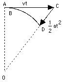
If the motion is followed just for a very brief moment, the path AB covered is so short that its curvature can be neglected, allowing one to view the motion as proceeding in a straight line, with velocity v. After a while, however, the difference between this motion and a straight-line one becomes obvious: the straight motion with velocity v would bring the particle to point C, at distance

AC = vt

while the actual motion brings it to some point D on the circle, whose center will be denoted by O.

It is useful to regard this motion as the sum of two separate motions: a straight-line motion from A to C, and then an added motion from C to D which returns the particle to the circle. As noted earlier (section on vectors), when a motion is the combination of two simpler motions, the resulting displacement can be obtained by deriving separately the displacements produced by each motion alone, then adding them together.

The added motion from C to D is the one of interest here. Its direction is always towards the center, and the distance CD covered by it--denoted here by x--can be obtained from the theorem of Pythagoras, applied to the triangle OAC (the calculation resembles the one which gave the distance to the horizon in section (8a)). In that triangle, OA = R, AC = vt, OC = R + x. Therefore

R2 + v2t2 = (R + x)2 = R2+ 2Rx + x2

Subtract R2 from both sides

v2t2 = 2Rx + x2 = x(2R + x)

If the time interval t is very short, x is much smaller than 2R and can be neglected by comparison. Then

v2t2 = 2xR

or

x = 1/2 (v2/R) t2

But by an earlier formula, in the section on acceleration, this is exactly the distance covered in time t by a motion with acceleration

a = v2/R

The above result suggests that steady motion around a circle, at least for a short time span, can be viewed as the sum of a straight-line motion with fixed velocity v, plus an accelerated motion towards the center of attraction, with the above acceleration, a.

The conclusion is correct, even though the derivation is somewhat irregular. The conventional derivation (like most of the theory of motions) requires the use of differential calculus, the study of changing quantities and of the way they change, as well as familiarity with vectors.

Centripetal acceleration and centripetal force

The acceleration a = v2/R towards the center, needed to keep an object moving in a circle, is called its centripetal acceleration, from Latin petere, to move towards. By Newton's laws, any acceleration requires a force. If a stone (or any other object) of mass m rotates with velocity v around a central axis O, at distance R from it, a force F must constantly pull it towards the center, and

F = ma = mv2/R

This is known as the centripetal force, and by continually pulling the stone, it keeps the string stretched. If the string would break--for instance, at point A in the drawing--the stone would continue with velocity v in a straight line along AC. And no, it would not fly outwards along OA, as some believe, even though that was the direction in which the string was stretched!


Next Stop: #20 Newton's Theory of "Universal Gravitation"

###############################

(20) Newton's theory of "Universal Gravitation"

The Moon orbits around the Earth. Since its size does not appear to change, its distance stays about the same, and hence its orbit must be close to a circle. To keep the Moon moving in that circle--rather than wandering off--the Earth must exert a pull on the Moon, and Newton named that pulling force gravity.

Was that the same force which pulled all falling objects downward?

Supposedly, the above question occured to Newton when he saw an apple falling from a tree. John Conduitt, Newton's assistant at the royal mint and husband of Newton's niece, had this to say about the event when he wrote about Newton's life:

    In the year 1666 he retired again from Cambridge ... to his mother in Lincolnshire & while he was musing in a garden it came into his thought that the power of gravity (which brought an apple from a tree to the ground) was not limited to a certain distance from earth, but that this power must extend much further than was usually thought. Why not as high as the Moon thought he to himself & that if so, that must influence her motion & perhaps retain her in her orbit, whereupon he fell a-calculating what would be the effect of that superposition...
( Keesing, R.G., The History of Newton's apple tree, Contemporary Physics, 39, 377-91, 1998)

If it was the same force, then a connection would exist between the way objects fell and the motion of the Moon around Earth, that is, its distance and orbital period. The orbital period we know--it is the lunar month, corrected for the motion of the Earth around the Sun, which also affects the length of time between one "new moon" and the next. The distance was first estimated in ancient Greece--see here and here.

To calculate the force of gravity on the Moon, one must also know how much weaker it was at the Moon's distance. Newton showed that if gravity at a distance R was proportional to 1/R2 (varied like the "inverse square of the distance"), then indeed the acceleration g measured at the Earth's surface would correctly predict the orbital period T of the Moon.

Newton went further and proposed that gravity was a "universal" force, and that the Sun's gravity was what held planets in their orbits. He was then able to show that Kepler's laws were a natural consequence of the "inverse squares law" and today all calculations of the orbits of planets and satellites follow in his footsteps.

Nowadays students who derive Kepler's laws from the "inverse-square law" use differential calculus, a mathematical tool in whose creation Newton had a large share. Interestingly, however, the proof which Newton published did not use calculus, but relied on intricate properties of ellipses and other conic sections. Richard Feynman, Nobel-prize winning maverick physicist, rederived such a proof (as have some distinguished predecessors); see reference at the end of the section.

Here we will retrace the calculation, which linked the gravity observed on Earth with the Moon's motion across the sky, two seemingly unrelated observations. If you want to check the calculation, a hand-held calculator is helpful.

Calculating the Moon's Motion

We assume that the Moon's orbit is a circle, and that the Earth's pull is always directed toward's the Earth's center. Let RE be the average radius of the Earth (first estimated by Erathosthenes)

RE= 6 371 km

The distance R to the Moon is then about 60 RE. If a mass m on Earth is pulled by a force mg, and if Newton's "inverse square law" holds, then the pull on the same mass at the Moon's distance would be 602 = 3600 times weaker and would equal

mg/3600

If m is the mass of the Moon, that is the force which keeps the Moon in its orbit. If the Moon's orbit is a circle, since R = 60 RE its length is

2 p R = 120 p RE

Suppose the time required for one orbit is T seconds. The velocity v of the motion is then

v = distance/time = 120 p RE/T

(Please note: gravity is not what gives the Moon its velocity. Whatever velocity the Moon has was probably acquired when it was created. But gravity prevents the Moon from running away, and confines it to some orbit.)

The centripetal force holding the Moon in its orbit must therefore equal

mv2/R = mv2/(60 RE)

and if the Earth's gravity provides that force, then

mg/3600 = mv2/(60 RE)

dividing both sides by m and then multiplying by 60 simplifies things to

g/60 = v2/RE = (120 p RE)2/(T2 RE)

Canceling one factor of RE , multiplying both sides by 60 T2 and dividing them by g leaves

T2 = (864 000 p2 RE)/g = 864 000 RE (p2/g)

Providentially, in the units we use g ~ 9.81 is very close to p2 ~ 9.87, so that the term in parentheses is close to 1 and may be dropped. That leaves (the two parentheses are multiplied)

T2 = (864 000) (6 371 000)

With a hand held calculator, it is easy to find the square roots of the two terms. We get (to 4-figure accuracy)

864 000 = (929.5)2       6 371 000 = (2524)2

Then

T @ (929.5) (2524) = 2 346 058 seconds

To get T in days we divide by 86400, the number of seconds in a day, to get

T = 27.153 days

pretty close to the accepted value

T = 27.3217 days

The Formula for the Force of Gravity

Newton rightly saw this as a confirmation of the "inverse square law". He proposed that a "universal" force of gravitation F existed between any two masses m and M, directed from each to the other, proportional to each of them and inversely proportional to the square of their separation distance r. In a formula (ignoring for now the vector character of the force):

F   =   G   mM/r2

Suppose M is the mass of the Earth, R its radius and m is the mass of some falling object near the Earth's surface. Then one may write

F   =   m   GM/R2   =   m g

From this

g   =   GM/R2

The capital G is known as the constant of universal gravitation. That is the number we need to know in order to calculate the gravitational attraction between, say, two spheres of 1 kilogram each. Unlike the attraction of the Earth, which has a huge mass M, such a force is quite small, and the number G is likewise very, very small. Measuring that small force in the lab is a delicate and difficult feat.

It took more than a century before it was first achieved. Only in 1796 did Newton's countryman Henry Cavendish actually measure such weak gravitational attraction, by noting the slight twist of a dumbbell suspended by a long thread, when on of its weights was attracted by the gravity of a third heavy object. A century later (as already noted) the Hungarian physicist Roland Eötvös greatly improved the accuracy of such measurements.

Exploring Further:

A site about the story that Newton's inspiration about the force of gravity came from observing an apple drop from a tree.

A detailed article: Keesing, R.G., The History of Newton's apple tree, Contemporary Physics, 39, 377-91, 1998

Richard Feynman's calculations can be found in the book "Feynman's Lost Lecture: The Motion of Planets Around the Sun" by D. L Goodstein and J. R. Goodstein (Norton, 1996; reviewed by Paul Murdin in Nature, vol. 380, p. 680, 25 April 1996).

An article in an educational journal about the subjects discussed above: The great law by V. Kuznetsov. Quantum, Sept-Oct. 1999, p. 38-41.


Next Stop: #21 Kepler's Third Law

###############################

(21) Kepler's Third Law

Besides the Moon, Earth now has many artificial satellites, put up by us earthlings for a variety of purposes. The calculation applied by Newton to the Moon can also be used for them.

Orbital velocity

Suppose the Earth were a perfect sphere of radius 1 RE = 6 317 000 meters and had no atmosphere. In principle, a satellite could then orbit just above its surface. The Earth would pull it downwards with a force F = mg, and because of the direction of this force, any accelerations would be in the up-down direction, too.

If the satellite is in a stable circular orbit and its velocity is V, then F supplies just the right amount of pull to keep the motion going. Which means

mg = F = mV2/RE

Dividing both sides by m shows that the mass of the satellite does not matter, and leaves

V2/RE = g

Multiplication of both sides by RE: gives

V2 = (g) (RE) = (9.81) (6 371 000) = 62 499 510 (m/sec2)

V = 7905. 66 m/sec = 7.90566 km/s = Vo

This is the velocity required by the satellite to stay in its orbit ("1" in the drawing). Any slower and it loses altitude and hits the Earth ("2"), any faster and it rises to greater distance ("3"). For comparison, a jetliner flies at about 250 m/sec, a rifle bullet at about 600 m/sec.

We again need a notation for square root. Since the HTML language does not provide one, we use the notation SQRT found in some computer languages. The square root of 2, for instance, can be written

SQRT(2) = 1. 41412. . .

If the speed V of our satellite is only moderately greater than Vo curve "3" will be part of a Keplerian ellipse and will ultimately turn back towards Earth. If however V is greater than 1. 4142. . .times Vo the satellite has attained escape velocity and will never come back: this comes to about 11.2 km/sec.

Kepler's Third Law for Earth Satellites

The velocity for a circular Earth orbit at any other distance r is similarly calculated, but one must take into account that the force of gravity is weaker at greater distances, by a factor (RE/r)2. We then get

V2/r = g (RE r)2 = g RE2/r2

Let T be the orbital period, in seconds. Then (as noted earlier), the distance 2 pr covered in one orbit equals VT

>
VT = 2 p r
V = 2 p r/T
V2 = 4 p2r2/T2
V2/r = 4 p2r/T2

and by the earlier equality

4 p2r/T2 = g RE2/r2

Get rid of fractions by multiplying both sides by r2T2

4 p2r3 = g RE2 T2

To better see what we have, divide both sides by g RE2, isolating T2:

T2 = (4p2/g RE2) r3

What's inside the brackets is just a number. The rest tells a simple message--T2 is proportional to r3, the orbital period squared is proportional to the distance cubes. This is Kepler's 3rd law, for the special case of circular orbits around Earth.

If you are not yet tired of the calculation, you may click here for turning the above into a practical formula.


Deriving a practical formula from Kepler's 3rd law.

Next Regular Stop: Frames of Reference: The Basics

###############################

(21a) Applying Kepler's Third Law

For circular orbits around Earth, we found

T2 = (4p2/g RE2) r3

with T in seconds and r in meters. The distance of a satellite from the center of Earth in meters is an inconveniently big number, even before we raise it to the 3rd power. We may however multiply the expression on the right by (RE3/RE3) = 1 and then rearrange the terms:

T2 = (4p2/g RE2) (RE3/RE3) r3 = (4p2RE/g) (r/RE)3

The ratio r' = (r/RE) is the orbital distance measured in units of the Earth's radius. That number is usually between 1 (at the Earth's surface, r = RE) and 60 (at the Moon's orbit, r ~ 60 RE).

Also, that ratio is always the same, whether r and RE are in meters, yards or nautical miles, as long as both r and RE are measured in the same units. The other term is calculated below, with multiplication denoted by blank spaces between parentheses; you may check it with your calculator.

(4p2RE/g) = (4) (9.87) (6 371 000)/9.81 = 25 638 838

Using computer notation for the square root

SQRT (25 638 838) = 5063.5 From this
'

T2= (5063.5)2 (r')3

T= 5063.5 seconds SQRT(r')3 = 5063.5 sec r'  SQRT(r')

This is the practical form of Kepler's 3rd law for Earth satellites. Our imagined satellite skimming the surface of the Earth (r' = 1) has a period

T = 5063.5 sec = (5063.5/60) minutes = 84.4 minutes

The space shuttle must clear the atmosphere and goes a bit higher. Say it orbits at r' = 1. 05, with SQRT(r') = 1. 0247. Then

T = (5063.5) (1.05) (1.0247) = 5448 seconds = 90.8 minutes

International communication satellites are in the equatorial plane of the Earth and have orbits with a 24-hour period. As the Earth rotates, they keep pace with it and always stay above the same spot. What is their distance?

Here T is known and we need to find r':

T = 24 hours = 86 400 sec = 5063.5 SQRT(r')3

SQRT(r')3 = 86 400/5063.5 = 17.0632

If all numbers on the last line are equal, their squares are equal, too

(r')3 = (17.0632)2 = 291.156

Now you need a calculator able to derive cubic roots (or else, the 1/3 = 0.333. . . power). This gives

r' = 6.628 earth radii

as the distance of "synchronous" satellites. The satellites of the global positioning system (GPS), by which a small, handheld instument can tell one's location on the globe with amazing accuracy, are in 12-hour orbits. Can you calculate their distance?


Next Regular Stop: #22 Frames of Reference: The Basics

###############################

(22) Frames of Reference: The Basics

Newton's equations describe and predict the way an object moves: but moves with regard to what?

To derive the motion of a penny dropped inside an airliner moving at 600 miles/hr (about 1000 km/hr)--should we calculate it with respect to the interior of the airliner, or with respect to the ground? Or does it make no difference what the choice is? In that case it would be best to calculate the motion with respect to the airliner, a much easier job.

And if a similar penny is let go inside an orbiting spaceship--should its motion be calculated relative to the interior of the spaceship, or relative to the Earth outside? Or perhaps, relative to the Sun, around which the Earth moves at much greater speed? Or relative to the galaxy, inside which the solar system has its own motion?

Each such choice is known as a frame of reference. Some possible frames are

    -- the interior of the airliner,
    -- the surface of the Earth, or
    -- the distant stars with respect to which the Earth rotates and moves.

Choosing the Frame of Reference

Obervations suggest that among all such choices, the frame of the stars (or of "the distant universe") is the proper one for Newton's equations.

However, this is not always the most convenient frame: for someone sitting in a moving airliner, in an orbiting spaceship or upon the rotating Earth, it is much easier to observe the way an object moves relative to its immediate surroundings than to figure out its motion relative to the distant universe! It is therefore often much preferable to derive the corrections which must be applied to the laws of physics in the local frame of reference, and then by taking those corrections into account, calculate the local motion.

Two rather typical cases are examined, here and in the next section. In those cases, relative to the rest of the universe, the local frame--

    (1) Moves with constant velocity in a straight line
    (2) Rotates at a constant rate around a fixed point.

(1) Constant velocity in a straight line

Suppose we sit in an airliner (or in a train, or on a ship) that moves with a velocity v0 , constant in direction and magnitude ("uniform motion"). Strictly speaking, this constancy should be with respect to the "absolute frame" of the distant universe. Here, however, we shall only assume constancy relative to the surface of the Earth, and later show that this gives a pretty good approximation to the "absolute frame."

How do observations differ in the two frames--the airliner cabin and the Earth? Very simply: any velocity v measured inside the airliner corresponds to a velocity
        v' = v + v0
with respect to the ground (in the most general case v', v and v0 are vectors and their directions may also differ).
And how about accelerations? Compare:

    --the acceleration a with respect to the cabin
        is the rate at which v changes.

    --the acceleration a' with respect to the ground
         is the rate at which v' changes.
However, because v and v' = v + v0 differ only by a constant velocity v0, the two change at exactly the same rate, so that a = a'. For the falling penny, both v' and v grow at the same rate g (about 9.8 meter/sec each second); the fact that a big constant velocity of 600 miles/hr is included in v' but not in v does not add anything to a', because "constant " means unchanging.

And because the accelerations are the same, so are the forces:

    In the frame of the plane     F = ma
    In the frame of the Earth     F' = ma'
and since a = a', it follows that F = F'. In short:

    All laws of mechanics remain the same in
    a frame moving at a constant velocity.

In other words: Newton's laws can be used in uniformly moving frames, as if those frames did not move. The theory of relativity modifies those laws when the magnitude of v or v0 approaches the speed of light in vacuum, but all motions studied here are much slower.

Now about the frame of the Earth: it is not the same as the frame of the distant universe. The rotation of the Earth around its axis has a small effect, most of which can be taken into account by a slight modification of the value of g (see next section). The accelerations added by the Earth's motion around the Sun (which were neglected) are counteracted by the Sun's gravity pull (also neglected), and both are small. It is thus not a bad approximation to regard the Earth as the ultimate frame of reference.


Next Stop: #22b The Aberration of Starlight

###############################

(22a) The Aberration of Starlight

Note: In this section, vector quantities are given in bold face letters.

Imagine yourself sitting in a boat, traveling over water with velocity u on a windless day. A small flag is attached to the boat's mast: in what direction will it point?

Seen from the boat, the flag always points to the rear, because in the boat's frame of reference, a wind with velocity -u seems to be blowing. It always points in the same direction.

What if the day is not windless? If a wind is blowing with velocity v? In the frame of the boat, the air now moves with velocity v - u , a vector sum, with the direction of v specified relative to the boat ("in the boat's frame"). The flag now points neither downwind, nor to the rear, but somewhere in between.

Suppose the boat now changes direction. In the frame of the boat u is still directed to the rear, but the wind now seems to come from a different direction, relative to the boat. Consequently, the direction of v changes, and the flag, pointing alongthe new v - u, has a different direction as well.

The Apparent Displacement of Stars

This section is about starlight, not about boats and flags. From Newton's days, astronomers have tried to find how far the stars were by the parallax method, using the diameter of the Earth's orbit as a baseline. They carefully measured the positions of stars at times half a year apart--representing two positions of the Earth separated by 300,000,000 km--and then checked whether the positions of stars in the sky changed. They soon found that, indeed, the positions did change. The trouble was that the observations did not make much sense.

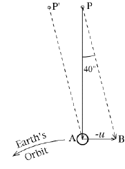
Jean Picard, one of the early French astronomers, made possible precise observations by introducing crosshairs in the telescope eyepiece. With this instrument he noted around 1680 that the observed positions of stars were not always the same. John Flamsteed, the astronomer royal of Britain--head of the Royal Observatory in Greenwich--confirmed those shifts. For instance Polaris, the pole star, seemed to travel annually around an ellipse whose width was 40", 40 seconds of arc.

As discussed in the section on parallax, that might suggest that the distance to Polaris was 1/40 of a parsec or less than 0.1 light year. However, the shifts in position did not occur at the times they were expected . The greatest shift of Polaris in any given direction occured not when the Earth's was at the opposite end of its orbit, as it should have been, but 3 months later.

For instance, in the drawing above, the apparent position of Polaris should have been shifted the furthest in the direction of "December" when Earth was in its "June" position, which is as far as it can go in the opposite direction. Instead, it happened in September, when the Earth had moved 90° from its position in June. In hindsight, the important quantity was not the displacement of Earth, but its velocity, which in September pointed towards the direction towards which Polaris was displaced.

Bradley's explanation

Astronomers were greatly puzzled, the more so when it turned out that all other stars near Polaris were shifted the same way. Then in 1729 the British astronomer royal, James Bradley, took a boat trip on the river Thames near London and noted the strange behavior of the flag on top of the boat's mast: it pointed neither downwind nor to the back of the boat, but in some direction in between, and when the boat changed course, that direction changed, too.

A sudden inspiration came to Bradley. The flag sensed a combination of two air flows, as seen in the frame of the boat: one due to the wind, the other due to the boat's motion. In a similar way, he reasoned, the velocity of the light coming from Polaris was modified in our own frame, by the added velocity of the Earth!

The velocity of light--today universally denoted by the letter c, as in "E=mc2"-- had been estimated in 1675 by Ole Romer, a Dane working at the Paris observatory, from a study of the eclipses of a moon of Jupiter. The velocity u of Earth in its orbit was also approximately known. Viewed from the frame of the moving Earth, the rest of the universe had a velocity -u, perpendicular to the velocity c of light coming from Polaris. Add these two up, as vectors, and you get the observed displacement.

    [You may well ask: when do we add u and when (-u)?
        When we are on the outside and observe an object moving with velocity u--e.g., an airplane in a cross-wind--we add u to its other motions.
        But when u is the velocity with which we, the observers, move, the outside world is moving relative to us with velocity (-u). Then (-u) must then be added to any other motion observed in the outside world.]
    Today we are well aware that adding -u to the velocity of starlight is in principle incorrect: when velocities close to c are added, formulas from Einstein's theory of relativity must be used. If we added -u to c in the usual manner, that would give a velocity larger than c, whereas by the theory of relativity the velocity of light is always c, regardless of how it is observed. However, it turns out that the displacement of the direction calculated by Bradley was the same as what relativity would give. Let us calculate it here the way Bradley might have done, ignoring relativity and using the same "pre trigonometry" introduced in the section on parallax.

    In the drawing shown here, let A be the Earth and AP the direction towards Polaris (the star itself is much more distant). The vector PA represents the velocity of light coming from Polaris at c=300,000 km/s. The vector AB represents the velocity -u of Polaris relative to Earth, equal in size to the Earth's velocity u=30 km/s in its orbit, but in opposite direction. (To simplify the calculation we assume AP is perpendicular to AB, in which case the apparent motion of the star is a circle; actually the angle is usually less than 90° making the apparent motion not a circle but an ellipse.) The point P ' indicates the apparent direction of Polaris as viewed from Earth, offset by an angle a=40" from its actual direction.

The length of each side in the triangle ABP is proportional to the velocity it represents; obviously its dimensions are not drawn to scale (it would be hard to draw a triangle with one side 10000 times longer than the other!). If the triangle is viewed as a pie-slice from a circle and the angle at P is denoted by a, we get

30/(2p 30,000) = 30 / 60,000p = a/360°

a= 10800 / 60000p = 5.7296 / 1000 degrees.

Each degree contains 60 minutes of arc (60') and each minute has 60 seconds of arc (60"), units unrelated to the minutes and seconds of time. Each degree thus equals 3600", giving

a = 3600" (5.7296 / 1000) = 20.6"

Half a year later the direction of u is reversed and the displacement is in the opposite direction, giving an annual range of about 40", as observed.

Aberration of the Solar Wind

A somewhat similar process is evident in the solar wind, a fast outflow (~400 km/s) of hot gas from the Sun. It originates in the Sun's corona, the highest and most rarefied layer of the solar atmosphere. That layer is so hot (about 1,000,000° C) that it does not achieve a stable static equilibrium, but boils off into a constant flow of rarefied, hot gas.

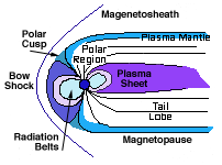
Strictly speaking, the solar wind is a plasma, a mixture of free electrons and of positive ions, atoms which have lost electrons in the violent collisions experienced in a 1,000,000 degree gas. Being a plasma, it can conduct electric currents and its particles can be steered by magnetic fields. The Earth's magnetism, in particular, deflects the solar wind flow, creating an elongated cavity known as the magnetosphere, from which the solar wind is excluded (see picture). On the side facing the Sun, the solar wind only reaches within 10-11 Earth radii of the Earth's center (65-70,000 km) before it is deflected sideways. On the night side, facing away from the Sun, a long "magnetic tail" extends to great distances, along the flow direction of the solar wind.


But what is that direction? In the reference frame of the Sun, the solar wind on the average streams radially outwards, with a velocity v of about 400 km/s (it does not change with distance). The Earth, however, orbits the Sun with a velocity u perpendicular to v, of about 30 km/s. Viewed from the frame of the Earth, a velocity -u is then added to v, so to us the solar wind appears to move with v' = v-u, as the drawing shows. The magnitude v' of the new velocity is found by applying the theorem of Pythagoras to the triangle ABC, which gives

(v')2 = v2 + u2     v' = 401.12 km/s

If b is the angle by which the solar wind is shifted in the Earth's frame, then

sin b = 30/401.12 = 0.0749         (or else, tan b = 30/400 = 0.075)

b = 4.289°

With a spacecraft exploring the distant nightside tail, as the Japanese "Geotail" did (at distances around 200 Earth radii), this effect must be taken into account if we wish to place the spacecraft in the tail and not next to it. Unfortunately, the direction of v also varies randomly by a few degrees, so that, while taking b into account helps, sometimes a point calculated to be inside the tail still misses it.

Plumes of Smoke

A steamship moves across the ocean with velocity u, in a wind with velocity v perpendicular to u. If u defines the x-axis and v the y-axis--in which direction does the plume of smoke trailing behind the ship move?

This problem becomes much easier if we work in the ship's frame of reference. In that frame and in the absence of wind, the smoke's velocity is -u. Adding the wind to the motion, the smoke's velocity becomes v-u (=v+(-u)), and that vector defines the direction of the plume of smoke trailing behind the ship. It will be in the (-x,y) quarter of the coordinate plane, and the angle a between it and the angle a between it and the (-x) axis satisfies

tan a = v/u         or else     sina = v/w, w = u + v

Trying to solve this problem in the frame of the ocean on which the ship is moving can get confusing, because we are not adding velocities but displacements. After each puff of smoke is released, it no longer shares the ship's velocity. Only in the ship's frame do motions become simple.

Comet Tails and the Solar Probe

At locations closer to the Sun, bigger aberrations of the solar wind can occur, because objects speed up as they approach the Sun (see Kepler's 2nd law!). This has an interesting effect on comet tails, which act very much like the plume of smoke in the preceding example.

Typically 1-20 km across, a comet is a collection of frozen gases and dust (a "dirty snowball") which had accumulated in the outer reaches of the solar system and was nudged into an sunward orbit. As the comet approaches the Sun, its frozen gases evaporate in the heat and a long tail is formed, pushed away from the Sun by sunlight and by the solar wind. The tail thus points behind the comet as it approaches the Sun but ahead of it when it recedes again.

Actually, two distinct tails are often observed--a dust tail pushed by the pressure of sunlight, and a plasma tail pushed by the magnetic field embedded in the solar wind (direct collisions between particles of the comet and solar wind are rare). The colors of the two tails differ: on comet Hale-Bopp in 1997 (see picture) the plasma tail was blue, a color produced by the ions which formed it, while the dust tail was white, the color of scattered sunlight.

The dust tail pointed in the direction of sunlight, as observed from the comet: it was probably shifted like the starlight observed by Bradley, but at an angle too small to be noted by eye. The plasma tail, on the other hand, pointed in the direction of the solar wind--again, as sensed by the comet. As seen above, Earth sees the solar wind shifted by about 4°, but for the comet the shift was appreciably larger, because it moved faster than the Earth, especially when it got closer to the Sun. The two tails therefore formed a distinct angle, as shown in the picture.

An even greater greatest aberration effect is expected aboard the solar probe, planned by NASA for observing the solar wind near the Sun. That spacecraft is expected to approach the Sun within 4 solar radii, avoiding melt-down in the intense heat by hiding behind a specially designed heat shield.

How then, one may well ask, can one shield out the sunlight and yet observe the solar wind, which like sunlight flows radially outwards? That is where aberration helps. At closes approach (perihelion) the solar probe would move at about 300 km/s, so that the solar wind moving at 400 km/s (but not sunlight) would be aberrated by about 37°, allowing it to reach detectors protected behind the heat shield.

                Postscript: Space Data by Laser

    Miniature satellites have trouble transmitting data to the ground. The satellite may be small, but the radio power it needs depends on the distance and cannot be arbitrarily reduced.

    One proposed solution was to use a laser on the ground. Instead of a radio transmitter, the satellite carries a corner reflector prism, which bounces the beam right back in the direction it came. This had been tried with a laser reflector left by astronauts on the Moon, and a big telescope on Earth did detect the returning beam. In the satellite, an electronic device using very little power would modulate the laser beam, encoding in it all the instrument data. Since the return beam retraces the path of the primary laser beam, the detecting station could be placed right next to the laser.

    Pretty neat--huh? Yes--but only until the proposers realized that aberration (like Bradley's) would shift the returning beam, because the satellite (unlike the Moon) moves quite rapidly. The shift may amount to tens or hundreds of meters, and its direction depends on the satellite's motion. Because of it, the idea was dropped.


Optional: #22b The Theory of Relativity

Next stop: #22c Airplane Flight

###############################

(22b) The Theory of Relativity

Relativity is beyond the scope of this exposition, but it deserves at least a brief discussion.

By Newton's laws, two frames of reference moving with constant velocity relative to each other observe exactly the same physical behavior. There exists no way to tell, which of them is moving and which one is at rest: there is no "absolute rest frame" and no "absolute (constant) velocity. " Everything is relative, and either frame can be chosen as reference benchmark.

In the 19th century the laws of electricity and magnetism were discovered, and suggesting that light itself was a related phenomenon, an electromagnetic wave (as is further discussed in the sections about the Sun). But for a while it seemed that by certain subtle effects, electromagnetic forces could distinguish whether a frame was in motion of not. Those effects were hard to verify, and when they were finally tried out, they did not work--they could not tell which system was in motion.

Albert Einstein then proposed, in 1905, the "principle of relativity" as a fundamental property of the universe. No matter what physical process was used, absolute motion at a constant velocity was undetectable. No loophole existed, not even through the laws of electricity and magnetism.

The trouble was, changing those laws (to plug the apparent loophole) would have upset the electromagnetic theory of light, for which ample evidence existed--e.g. radio waves. Einstein therefore suggested that those laws were correct and instead, Newton's laws were the ones needing to be modified--even though those laws already did hold that absolute motion was undetectable. Furthermore, time intervals measured in different moving frames of reference did not always agree--time became "relative."

The modifications suggested by Einstein only became significant near the velocity of light, and in day-to-day phenomena it could be ignored. As the velocity of light was approached, however, inertia (i.e. mass) increased, making it harder and harder to accelerate any matter and setting that velocity as an absolute limit, which no material object could exceed.

  All those predictions have been amply confirmed by experiments, and particle accelerators in particular have left little doubt that particles get more massive as they approach the velocity of light, and that velocity is indeed an upper limit which cannot be passed. The relativity of time was demonstrated when it was found that muons--particles with a lifetime of about 2 microseconds--produced by fast atomic nuclei ("cosmic rays") high in the atmosphere, survived much longer and generally reached the Earth's surface, because in the frame of reference of the Earth, their lifetime seemed longer.


Next Stop: #22c Airplane Flight

###############################

(22c) Airplane Flight

    This section contains examples from aviation, of wing sweep-back and variable propeller pitch, to illustrate frames of reference, vector addition and vector resolution.

Basics of Aviation

  Airplanes are held up by the way air pressure rearranges itself when air flows over the wing of an airplane.

  Any object immersed in a fluid (in air or water, for instance) experiences a pressure on all its surfaces, a force on each unit of area due to the weight of air or water stacked up above it (even if that surface faces sideways or down). In the absence of motion--e.g. when the airplane is standing on the runway--a wing experiences equal pressure on its top and bottom, and therefore tends to move neither up nor down.
  With the airplane in flight, an air flow passes over the wing, and the shape of the wing's cross section--curved above, flat or nearly flat below--reduces the pressure on top, causing the extra pressure from below to exert a lifting force ("lift"). The lift increases if the front of the wing is raised slightly, biting into the moving air at a small angle ("angle of attack"), and for a given lifting force, this kind of wing produces much less air resistance ("drag") than a flat kite.

Frames of Reference

      But wait a moment--isn't it the airplane that is moving, not the air?

  Depends on one's frame of reference!  In the frame of the air or the ground, the airplane is indeed in motion. But one could also calculate everything in the frame of the airplane, where it is the air that is moving. As long as the airplane flies in a straight line with constant velocity, the same laws apply.
    (In the sections that follow it will be shown one can also extend this to flight in a curved path, as long as one includes the centrifugal and Coriolis forces, "intertial" forces which only appear in calculations in a moving frame.)
Working in the airplane's frame, for instance, makes it easy to include effects of wind, whose velocity is simply added (vector addition!) to the air velocity sensed by the airplane .

  To test how a wing will perform in flight, instead of making it move in still air, one may equally well mount it in a laboratory and blow over it a stream of air. The physical processes are the same. That is the principle of the Wind Tunnel--a box with a fan that blows air into it (or better, sucks it out, which produces a smoother flow), inside which wing sections can be mounted and tested.

  The wind tunnel built by Orville and Wilbur Wright, inventors of the first practical airplane, was not the first--a few others already existed at the time--but it was the first one to be actually used to design a flying machine. The Wrights used small-scale replicas of wings and measured their lift and drag by means of delicate balances (a theory exists on the behavior of scaled models). A reconstruction of their original wind tunnel, as well as displays of the balances with which they measured lift and drag, can be seen at the Franklin Institute museum in Philadelphia. Click here for a site describing that exhibit, with further links that can also help you construct your own wind tunnel.

Swept-back wings

   The wings of small airplanes, whose speed is limited, are generally straight, a design which offers the greatest efficiency. On jet airliners, on the other hand, and on fast military airplanes, wings are often swept back; some military jets can even rotate their wings--straight-out for greatest efficiency when taking off and landing, swept back for flight near the speed of sound.

At the speed of sound, the air resistance ("drag") increases steeply, because air cannot get out of the way fast enough and therefore becomes compressed and heated. Heat is a form of energy, and to produce it, something else has to give up energy--in this case, it is the motion, producing increased drag; the "lift" of the wing also suffers. Actually, those problems begin well before the speed of sound is reached, because part of the flow above a wing has extra speed and can reach that speed even before the airplane does.
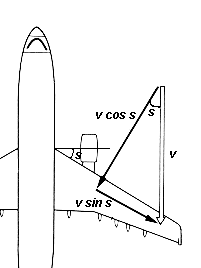
  But one can "cheat" to some extent by sweeping the wing backwards, by some angle s. Now, even though the air advances towards the airplane with velocity v, the velocity vector can be resolved into the sum of two perpendicular components--a flow velocity v sin s directed along the wing and a flow velocity v cos s directed perpendicular to it. Both are smaller than v, since both (sin s) and (cos s) are always smaller than 1.

  One can now argue that the flow of air along the wing will not cause any pile-up, nor any lift or drag, and ignore it. Only the perpendicular flow v cos s has such effects, and in a crude theory, the performance of the wing depends only how near the speed of sound that perpendicular component gets. Thus sweepback allows the airplane to fly a little bit closer to the speed of sound, without incurring associated penalties; the Airbus 320, for instance, has a sweepback of about 25 degrees. For a detailed website discussion of swept-back wings, click here

Propellers

   Airplane propellers act like small rotating wings, whose "lift" pulls the airplane forward (the pulling force is known as thrust). Possibly the greatest benefit derived by the Wright brothers from their wind tunnel was the help they got, not in planning their wings (a crude design, limited by available technology) but in the design of their propellers, which were twice as efficient as any others of their time.

  Again, it is more convenient to regard the propeller as static and the air as moving. It is also permissible to ignore the fact that propeller blades move around a circle, by considering only a short segment of that circular motion, over which the motion is nearly in a straight line.

    (Note however that each part of the propeller blade moves with a different speed. One should divide the propeller into sections, each with its distance from the central shaft, and study separately the forces on each section. Here let us concentrate on the tip sections of the blades, whose velocity v1 is the greatest and which therefore generate the greatest thrust.)
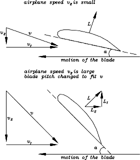
  What complicates the situation is that the airplane itself, too, is moving.. Again, this can be studied from the frame of the airplane, which sees the air rushing towards it with some velocity v2. From the frame of the blade-tip (top drawing), air is blowing at it with a velocity consisting of two mutually perpendicular components, v1 due to its own motion and v2 due the the airplane's forward motion.

  Consider the propeller's action before the airplane begins to move (v2=0). The lift L on the blade, which provides the airplane's thrust, is perpendicular to the blade's motion (or nearly so), and pulls the airplane straight ahead, as is required.

  Next suppose the airplane is flying at a moderate velocity v2. Now the propeller no longer senses a head-on velocity v1, but a velocity v hitting the blade at an angle slanting from the front (top of the figure). This was not a serious problem in the earliest airplanes, because they flew rather slowly. For them v2 was always much smaller than v1, and a one-piece metal or wooden propeller, with its blade slightly rotated to face v at the airplane's usual cruising speed (or slighly more, to provide a small angle of attack), worked quite well at other speeds, too. Many small airplanes today still use such propellers.
  Faster airplanes, however, need propellers with adjustable blades, able to increase the angle ("pitch") at which they "bite" into the air as the flight speed increases, so that they always face into the combined velocity v due to their own motion and that of the airplane. One can not compensate by increasing the speed v1 of the blade, because as the propeller tips reach the speed of sound, their efficiency drops markedly (and the noise they produce rises!)

  Adjustable blades ("variable pitch propellers"), more expensive and complicated than one-piece propellers, have long been standard equipment on the faster propeller airplanes. But even they hit a limit. Suppose the airplane moves at the same speed as the propeller tip, that is, v2 = v1. The tip of the blade then needs to be rotated into the direction of motion by 45 degrees into the direction of motion (bottom drawing). Two disturbing trends now become evident.

  First of all, as seen from the "vector addition triangle" and the theorem of Pythagoras, the total velocity v sensed by the blade is considerably faster (by about 41%) than either of its two component velocities, pushing it closer to the speed of sound and its associated problems. And secondly, the lifting force L on the blade is also rotated by 45 degrees! Only the component L1 pulls the airplane forward--the other component, L2, actually opposes the rotation of the propeller and demands extra power from the motor, power that serves no useful purpose.

  Because of such problems, propeller airplanes have never even approached the speed of the jets. The faster propeller-driven fighter airplanes of World War II flew at about 370-400 mph. The speed record for a purely propeller-driven airplane, 463 mph, was attained in Germany before the war, in 1939, and was never exceeded.

And by the way...

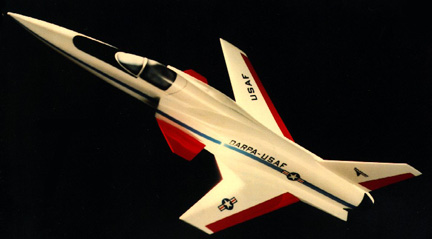
  Wings on jet airplanes are swept back, to reduce the velocity component flowing perpendicular to the wing. Couldn't the same effect be produced by sweeping the wings forward? It is possible and was done on NASA's X-29 experimental aircraft (pictured below; more about it, here). However, the airflow acting on a flexible swept-forward wing tends to twist it in a way which reduces its stability, and for that reason the swept-back design is generally preferred.

A NASA engineer, Robert T. Jones, has experimented with a related idea--one wing swept forward, the other one back. Such a wing can be attached to the airplane by a pivot. For take-off and landing, the wing is perpendicular to the fuselage, operating at its greatest efficiency and giving the aircraft a conventional appearance. Then at cruising altitude, as the airplane speeds up, the wing is rotated around its pivot--one tip points forward, one back. Would that work?

Work with radio-controlled models has shown that it actually would (a full-scale piloted model was also considered). Unfortunately, the tilted-wing configuration only flew well in a straight line--attempts at turning the airplane put it in a barrel roll. The benefits did not outweigh the risk of the wing getting stuck and the airplane being unable to land, and the design was not further pursued.

Postscripts: In the 1999 Oshkosh air show, VisionAire corporation showed a redesigned version of its Vantage business jet, with moderately forward-swept wings. A picture can be found on p. 78 in the 16 August 1999 issue of "Aviation Week."

  Also, the front of the 29 May issue of "Aviation Week." carries a picture of Sukhoi 37, a new Russian fighter airplane with forward-swept wings. An article on this airplane can be found on pages 52-4 of the issue.


Optional Extension:   #22d   More on Airplane Flight: How High? How Fast?

Next Stop: #23  Accelerated Frames of Reference: Inertial Forces

###############################

(22d) Airplane Flight:
          How High? How Fast?

An airplane stays aloft because of the flow of air above and below its wing. That flow creates an upward "lift" force opposing gravity, which keeps the airplane from falling.

Streamlining

The cross-section ("profile") of an airplane wing must meet two demands. First, its rear must taper down to a thin edge, like a wedge. That is where two air flows join together, from above and below the wing, and such "streamlining" assures that they meet smoothly, without swirling flows which increase air resistance. In contrast, an open parachute, whose rear is a half-sphere, creates a great deal of swirling behind it and has a large resistance; trucks which end abruptly in a high cargo door similarly encounter relatively high air resistance.

    [Contrary to intuition, the shape of the front is less critical. Perhaps our intuition owes too much to the bows of ships, which come to a sharp edge in order to cut through surface waves. Deep-sea nuclear submarines have blunt spherical fronts, just as airships.do.]

Lift and Drag

Streamlining reduces resistance ("drag" in aviation language). The second requirement, needed to produce lift, is that the wing be non-symmetrical--flat on the bottom but rising in a curve on top. That shape speeds up the air flow over the top, which reduces the air pressure there, and when the pressure on the bottom of the wing is larger than the one on thetop, the net result is an upward force.

Researchers since the Wright brothers have used wind tunnels to test models of different wing profiles, and have this way identified cross sections suited for various types of flying. They also found that the lift force produced by a wing was roughly proportional to the density D of the air and to the square of the velocity v of the airflow over it:

L   =   A D  v2

Here L is the lift in kilograms, D the air density (about 1.3 kg/meter3 at sea level) and v may be in meter/sec, mph or km per hour--whatever one prefers. The factor A depends on the profile of the wing, the wing's length and its width: a larger wing obviously gives a larger lift. It also depends on the "angle of attack" at which the wing faces the airflow: we assume that angle to be the one with the most economical operation, when the lift/drag ratio is at its largest.

One can increase the lift by increasing the angle of attack (as one does with a kite), but at the price of a much greater drag. Furthermore, if the angle is too steep, the orderly flow above the wind is disrupted and the wing "stalls, " suddenly losing much of its lift. Many airplane crashes have been traced to sudden stalls.

How high, how fast?

Suppose you design an airliner weighing W kilograms. In level flight, of course, lift must balance the airplane's weight

L   =   W
so
A D v2   =   W

The value of W is set by A--in other words, the wing must be long enough, wide enough and efficient enough to keep the weight W of the loaded airliner in the air.

How high and how fast should the airliner fly? Passengers want to reach their destination quickly, so designers aim at a high "cruising speed." However, passengers also value safe landings, and hence the landing speed should be slow.

Speed is the main reason why airliners fly at an altitude above 30,000 feet or close to 10 kilometers. Air density decreases to about 1/2 with each added 5 km of altitude, so at 10 km, D is about 1/4 its sea-level value and an airplane can double its speed to generate the same lift, with the same drag (which also grows like Dv2). The main reason airliners have pressurized cabins is to allow them to fly higher in order to fly faster.

How fast? The practical limit seems to be around 600 mph (960 km/hour). Any closer to the speed of sound (1200 km/h = 746 mph, varies with temperature) and the air flow above the wing creates shock fronts which increase drag and reduce lift. Even to get that far, swept-back wings are needed.

Landing safely

A speed of 600 mph at an altitude of 10 km seems to imply a sea-level landing speed of 300 mph (D is 4 times larger, so v can drop to 1/2). That is still too fast--even the space shuttle is said to land at 270 mph. One could fly at 70,000 feet (about 20 km) the way the U-2 reconnaissance plane does, and land (even without changing the angle of attack) at 150 mph. However, to create the necessary lift in the thin air at that height, A must be much bigger--that is, the wing must be much larger--or else the weight W must be reduced (or both). That was done for the U-2, a light-weight airplane with a very long and efficient wing, but such a design would not work on the scale of an airliner.

The practical solution is to increase the angle of attack during landings, and to temporarily increase the size of the wing. If you ever sat near the window of a landing airliner, you may have noted extra wing surfaces sliding out on the final approach, to provide more lift--and if you watched such an airliner from the ground, you would see that these surfaces extend downwards from the wing, at a steeper angle. All that of course makes drag much larger, but a landing airplane must anyway get rid of its extra speed.

All these allow the airliner to land at about 150 mph. Landing is actually a precision maneuver, in which the airliner (ideally) runs out of airspeed just before its wheels touch the ground. Glide slope radars and other navigation aids make it possible, thousands of times each day.

Non-stop around the world--How high? How fast?

One of the more memorable feats in aviation was the non-stop non-refuel flight of the Voyager airplane around the world, in December 1986. Designed by Burt Rutan and piloted by his brother Dick and by Jeana Yaeger, the plane now hangs above the lobby of the National Air and Space Museum in Washington.

Initially the hope was to have a pressurized cabin and to fly at 25,000 ft., but weight limitations precluded that, so that a slower, lower flight was undertaken, lasting 9 days. The take-off weight of "Voyager" was 9700 pounds, and to lift such a heavy airplane, it used two engines--one pushing and one pulling--to reach the required airspeed of 138 mph.

Halfway through the flight, as fuel was used up, less lift was needed. Therefore one engine was shut off, airspeed was allowed to drop to 79 mph, and to avoid reducing it even more, the flight altitude was raised to 11-12,000 feet. As a result the second half of the flight was much slower than the first, and much harder on the sleep-deprived pilots. They had, however, no other choice--flying faster would have required a less efficient wing angle, and would have wasted too much fuel.


Next Stop: #23  Accelerated Frames of Reference: Inertial Forces

###############################

Note: This lesson uses vectors, and some way of denoting them on the board and in the notebook must be agreed on by the class. In this lesson plan, all vector quantities will be underlined.


(23) Accelerated Frames of Reference: Inertial Forces


            The other case of a moving frame of reference studied here is an accelerated frame of reference.

An earlier section described motion in a circle and introduced the centripetal force which makes such motion possible. That is a force towards the center of rotation, of magnitude

    Fcentripetal = mV 2/R
where R is the radius of the circle of rotation and V is the velocity of motion around it.

To anyone who has not studied motions and accelerations, "centripetal" is probably a new word. However, most people are aware of the outwards-pushing centrifugal force, the force which flings you away from the center of rotation in a car speeding around a corner. In a popular carnival ride, that is the force which pushes you against a rotating drum, holding you in place even when you are upside down. What is the connection?

Inertial forces

As will be seen, the centrifugal force is not a "real" force, in the sense that in any motion calculated "in the frame of the universe" (or in one moving uniformly with respect to the universe) it does not appear at all. In such a frame, if an object moves around a circle, a centripetal force is needed to maintain that motion--otherwise it flies off at a tangent, with constant velocity along a straight line.

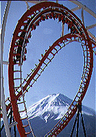
Unfortunately, if you sit (for instance) in a roller coaster car going around a vertical loop, as in the picture above, from an amusement park in Japan, it is a bit difficult to visualize your motion with respect to the fixed Earth. It is much simpler to orient yourself with respect to the car in which you sit.

The roller-coaster car, however, is undergoing various accelerations, and as a rule, when we try to apply the laws of motion inside an accelerated frame of reference, extra forces enter the picture, known as inertial forces. You could call them "fictitious" forces, if you wish, because when the same motion is calculated in the frame of the outside world, they do not appear at all. Inside the accelerated frame of reference, however, they can't be told apart from real forces, and they need real forces to balance them.

The centrifugal force is one such force, but before studying it, we consider a simpler case. You are sitting in a bus, moving in a straight line. Suddenly the driver applies brakes and all passengers feel pushed forward. Why?

Unit Vectors

Forces are vectors, and F=ma is a vector equation. Rather than separate it into components, we introduce here a simple notation which allows vectors to be handled as single entities.

Suppose we work in an (x,y) system of coordinates, with x pointing down and y pointing in the direction of the motion of the bus (if you are used to an (x,y) system with the y-axis pointing up, rotate it clockwise by 90°). Then unit vectors xu and yu would then be vectors of unit length, in the x and y directions.

[Note: marking unit vectors with a subscript "u" is a non-standard notation, forced by the limitation of the HTML code used on the world-wide web. The standard notation is a caret on top, as in â, ê or û, but unfortunately, HTML does not allow carets to be placed on most letters. If presenting this material in a classroom, it may be better to use carets.]
So, in (x,y) coordinates, a vector V with components (Vx,Vy) could be written

V = Vx xu + Vy yu

The Decelerating Bus

Let us examine the forces on some passenger inside the bus. Two forces are involved: the weight F1=mg yu, pulling the passengers down, and the reaction F2 of the seat, which does not allow any motion in that direction. As long as the bus moves in a straight line and with a constant speed, these two are the only ones that matter and we get as condition of equilibrium

F1+ F2 = 0

What happens when the brakes are applied? Let us look first from the frame of reference of the outside world. If the bus accelerates forward, the acceleration is

a = a yu
When the brake is applied, therefore

a = - a yu
and the forces on a mass inside must obey Newton's law

F1+ F2 = - ma yu

Note that now, if equilibrium is to be maintained, the forces must change. The weight F1 is fixed, and to keep the balance of the equation (as well as of the passenger), F2 must change. For instance, the passenger may grab the seat in front, pushing her or his body back, with a force equal to the acceleration added on the other side of the equation.

To see how the situation looks in the frame of the bus, we add +ma yu to both sides. On the right now, what is added equals what is subtracted, leaving zero, so the equation becomes

F1+ F2 + ma yu = 0

This may be interpreted in the frame of the decelerating bus as follows. For forces to stay in equilibrium, all forces (as before) must add up to zero, but now they must include an inertial force mayu pushing forward, in the direction of yu. This inertial force is only felt in the moving frame. You may call it a "fictitious force" if you wish. But when you need a seatbelt or an airbag to stop it from throwing you through a windshield, it seems real enough!

Taking Off

If you ever take a trip on a jetliner, notice how during take-off you are pushed back in your seat. That is the inertial force acting in the frame of the accelerating airplane. In a decelerating bus, you are pushed forward, but in an accelerating airplane you are pushed back.. For a simple experiment, take with you a weight on a string (a fishing sinker or a stack of screw-nuts does fine) and let it hang before take-off, defining the "down" direction. During take-off, the string will slant backwards, by perhaps 5-10 degrees.

All this is rather mild compared to the inertial forces felt by astronauts in the space shuttle during launch. The shuttle accelerates at about 2-3g, so the added force felt by the astronauts, in their frame of reference, is 2-3 times their weight.


Next Stop: #23a The Centrifugal Force

###############################

Note: In this lesson, as in the preceding one, all vector quantities will be underlined.


(23a) Frames of Reference: The Centrifugal Force

The schoolboy, rising early for his examination work, puzzled it out for himself .... "Centrifugal, centripetal," he said, with his chin on his fist. "Stop a planet in its flight, rob it of its centrifugal force, what then? Centripetal has it, and down it falls into the sun! And this--!"
                H.G.Wells, The Star


    We now come back to motion in a circle.

    The Centrifugal force

    Motion in a circle is an accelerated motion. Therefore, if we study it in the rotating frame of reference, we can expect inertial forces to appear--like the ones discussed in the preceding section.

      Suppose a person sits on a bus, moving in a straight line with constant speed v. As before, the forces involved are the passenger's weight F1 and the reaction force of the seat F2, and in the absence of acceleration, the two cancel:

    F1+ F2 = 0

    Suddenly the bus makes a sharp turn, following part of a circle of radius r. If the passenger's body is to stay in the seat as before, an extra force must be added, to keep it from continuing in a straight line (its natural tendency). If ru is a unit vector (unit vectors are defined in the preceding section) directed outwards from the center of rotation, along the radius r, the force F2 exerted by the seat must increase to provide the centripetal force -(mv2/r)ru that makes the passenger follow the motion of the bus:

F1+ F2 = - (mv2/r) ru

  The bus and the seat now constrain the passenger's body to follow part of a circle, and to do this must pull it towards the center. To stay in place (that is, balance the above equation), F2 on it must be increased by an additional force in the direction of -ru, towards the center of the curve.

How does this same event look in the frame of the bus? Adding (mv2/r)ru to both sides of the equation gives, in a similar way to what was done before

F1+ F2 + (mv2/r) ru = 0

Equilibrium is attained and the passenger stays in place, if the equation above is satisfied. This can be viewed as the equilibrium between 3 forces-- F1, F2 and the centrifugal force (mv2/r)ru directed along ru, radially outwards.

This can easily be generalized to any frame of reference moving around a circle:

    Equilibrium exists in the rotating frame if all forces balance, including an inertial "centrifugal" force (mv2/r)ru.

Examples

When calculating the motions of the oceans and the atmosphere, it is much easier to use reference points on the rotating Earth and add a centrifugal force to all equations. That is one reason why the observed acceleration g due to gravity departs from the average value of 9.81: at the equator, the centrifugal force must be subtracted from the force of gravity, while at the pole no centrifugal force exists. Observations of g give values from 9.78 at the equators to 9.83 at the poles, but the centrifugal force is responsible for only part of that difference. The rest arises because the Earth is not a perfect sphere: the centrifugal force of its rotation causes its equator to bulge out, making the surface there more distant from the Earth´s center and thus weakening the gravitational pull.
    (You may also note that the direction of the centrifugal force is away from the axis of rotation, and therefore it points away from the Earth´s center only at the equator. One therefore expects at all other points (except for the poles) a very slight difference between the vertical as defined by a plumb line and the direction to the center of the Earth.)

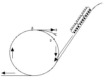
Another example is the "loop the loop" feature found on some roller coasters in amusement parks. There the track descends on a long slope and then, at the bottom, turns in a complete circle (drawing) before leveling out again. At the point marked "A" the riders are briefly turned upside down, but no one ever falls out. How come? And (in the absence of friction), what is the minimum height h of the starting point S above A needed to ensure that the car passes safely through A?

This is easily solved in the frame of the moving roller-coaster car. In that frame, the forces on the car at the top of the loop are
  • The weight -mg ru (downwards, along -ru at this point.)
  • The centrifugal force (mv2/r) ru, and
  • The force F2 exerted by the rails.

The car will just barely manage to get past point A if gravity and the centrifugal force are exactly equal, so that the rails need to exert no extra force:

-mg ru + (mv2/r) ru = 0

The two vectors are both along ru (with signs giving the direction), so everyhing reduces to an equation between ordinary numbers:

-mg + mv2/r = 0

Suppose now the car has come down from a height h above the highest point in the loop. It has

  • lost potential energy mgh, and
  • gained kinetic energy mv2/2
so from conservation of energy

mgh + mv2/2      or       2mgh = mv2

Substituting
-mg + 2mgh/r = 0

Divide by mg, add +1 to both sides:

2h/r = 1      then multiply r/2 to get h:       h = r/2

The car must have started at least half a loop radius above A.
Click here for an optional section handling the same problem by using the centripetal force.

Exploring Further:

About a classroom demonstration of "loop the loop" with a "hot wheels" toy car--click here.

Site about roller coasters--the biggest, highest, the one with the most loops (8) and the one with the biggest loop ("Moonsault Scramble" in Japan, pictured at the beginning of this page)--click here.


Next Stop: #24 Rotating Frames of Reference

###############################

(24) Rotating Frames of Reference in Space and on Earth

"Weightlessness"

An astronaut in low Earth orbit moves in (approximately) a big circle extending around the Earth. The acceleration required for such motion is provided by gravity

mg(RE/r)2= mv2/r

where the astronaut's weight mg on the Earth's surface at r = RE is adjusted on the left side for the greater distance. That is of course the same equation as the one used to demonstrate Newton's study of gravity. However, it can also be written

mg (r/RE)2 - mv2/r = 0

That can be interpreted as stating that in the astronaut's frame of reference, all bodies are subject to two forces, gravity and the centrifugal force, and the two are in perfect balance, adding up to zero.

It is sometimes claimed that astronauts in space are in a "zero gravity" environment, but actually they are still very much under the influence of the Earth's gravity. True, the astronaut observes no tendency at all to fall towards Earth, but the reason is different and can be stated in one of two ways:

  1. Gravity is already kept fully occupied by supplying the ongoing acceleration (the first of the above equations); or

  2. The force of gravity is perfectly balanced by the centrifugal force (second equation).
Take your choice!

"Zero g" Simulation in an Airplane

What if the spaceship's orbit is not circular but (say) elliptic? It makes no difference. If the force of gravity at distance r is

F = mg(RE/r)2

Then the equation of motion of an object subject to F alone is

ma = mg(RE/r)2
or
a = g(RE/r)2

The acceleration a is what a spacecraft in orbit experiences, viewed from the fixed frame of the Earth. In a circular orbit of radius r it equals v2/r, while in an elliptic orbit it may have a different magnitude and different direction, which could also be calculated. The important thing to note here is that an astronaut inside that spacecraft is subject to the same gravity and therefore undergoes the same acceleration as the spacecraft itself. Viewing the astronaut's motion in the frame of the moving spacecraft, the astronaut is not pulled towards the floor of the cabin or in any other direction, and therefore has the impression that gravity has been eliminated.

Suppose that instead, the astronaut rode inside a freely falling cabin, near the surface of the Earth. There, too

ma = mg(RE/r)2

but since r is very close to 1 RE, we may set that ratio equal to 1 and get simply

a = g

The cabin falls with acceleration g, but the passenger also falls with the same acceleration, so again, no force exists that pushes the passenger towards the floor of the cabin. Acting on cues from the surrounding cabin, the passenger will again get the illusion that gravity did not exist.

It makes no difference if the cabin started with a constant velocity--e.g. tossed upwards with an initial velocity u and with an initial horizontal velocity w--because neither of these affects the forces and accelerations. Both cabin and passenger would still be accelerating downwards at a=g, creating an illusion of zero gravity.

If this experiment were actually conducted, that illusion and also the cabin would all too soon be shattered by contact with the hard ground below. Furthermore, air resistance would soon reduce the cabin's acceleration below g. The passenger inside, still subject to a=g, would then overtake the cabin, a process which would appear in the frame of the cabin like a partial return of gravity.

However, the same experiment can be safely performed aboard a high-flying aircraft, which could match any air resistance by the thrust of its engines. By following a programmed parabolic path similar to that of a projectile subject to gravity alone, such an aircraft can create--for a limited time--a zero-gravity environment inside its cabin.

NASA has done so with a KC-135 aircraft, a 4-engine jet nicknamed "The Vomit Comet" because its sudden transition to zero-g makes some passengers quite airsick. The airplane can produce a temporary zero-g environment in its cabin, and is used for training astronauts and for short experiments on zero-gravity phenomena. The cargo space inside it is completely covered with padding, and a "zero gravity" illusion can be maintained for about 20-30 seconds. For pictures and details, link here.

The Coriolis Force

 Wheel-shaped space
 station with visiting
  winged spaceship
(Von Braun's, from the early 1950's)

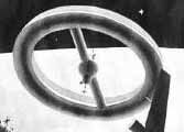
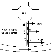
The science-fiction film "2001: A Space Odyssey" featured spinning space station, whose rotation provided the crew with "artificial gravity." It was a wheel-shaped structure, with hollow spokes connecting the wheel to a cabin in the center (drawing). The cabin in the middle was where transfers between the station and visiting spacecraft took place. Click here for more on that design.

Given such a rotation, something like gravity would indeed be produced, with "down" being towards the outside (Larry Niven expanded that notion into the fanciful science-fiction novel "Ringworld" and its sequels). When calculating this effect it is simplest to use the station's frame of reference and add a centrifugal force to all other forces there.

However, when one moves in this rotating environment, especially motion up and down the spokes, an additional force is encountered, named for the Frenchman Gaspard Gustave de Coriolis (1792-1843).

Imagine an astronaut moving along one of the spokes, say from point A in the drawing to point B--most likely, climbing a ladder, since such motion goes against the station's "artificial gravity." At any point, as viewed in the frame of the outside world, the astronaut is also rotating around the station's axis.

At both point A and B, the rotation is in the same direction, but at B it is slower, because that point is nearer to the axis of rotation and therefore describes a smaller circle. What happens at B to the extra speed the astronaut had at A? According to Newton's first law, loosely applied, the astronaut would tend to keep that extra speed and would therefore be pushed agains the side of the spoke (direction of the arrows). That push is the Coriolis force. When the motion is in the opposite direction, from B to A, the direction of the force is. . . the same or reversed? Work it out yourself!

Swirling Water in a Bathroom Sink

From time to time the claim is made that water draining from bathroom sinks swirls in opposite directions north and south of the equator.

The physical principle is sound, but the actual effect is so microscopic that it is unlikely to be observed in the draining of bathroom sinks. On the other hand, the same effect is very important in large-scale swirling of the atmosphere, in hurricanes and typhoons as well as in ordinary weather patterns.

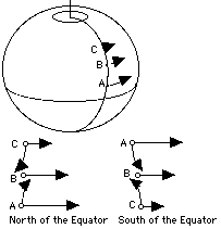
The Earth, when viewed from above the north pole, spins counter-clockwise. Imagine 3 points in the northern hemisphere, at the same geographical longitude (drawing)--A closest to the equator, B somewhat poleward and C further poleward still. Each of these points covers in one day a full circle around the Earth's axis: A has the biggest circle, goes the greatest distance and therefore moves the fastest, B with a small circle moves more slowly, and C is even slower. The points are redrawn on the right on a magnified scale, with arrows attached to indicate the directions and magnitude of their velocities.

Now imagine that for some reason a low-pressure area has developed in the atmosphere at point B. Air will tend to flow towards B from both A and C, but as it does so, it tends to keep its speed of rotation, like the astronaut in the preceding example. Thus the actual flow from A (dotted arrow) ends up ahead of B, deflected to the right (in the rotating frame), and the flow from C ends up lagging behind B, deflected to the left. The result is the same as the addition of a counterclockwise swirling around B.

Imagine next that the points are moved to the southern hemisphere, reversing their order, so that A remains closest to the equator and is still the fastest-moving point of the three. The flow from A is still deflected to the right and the one from B to the left, but because the north-south order of the points is now reversed, the resulting swirling is clockwise.

 A hurricane viewed from space.

Big storms in the atmosphere are usually centered on low-pressure areas and conform to those rules. This was first observed in weather patterns in 1857 by Christoph Buys-Ballot in Holland, though William Ferrel in the US had predicted the phenomenon using arguments like the ones given here.

But don't expect to observe the effect in bathroom sinks. Water draining from a sink will usually swirl, because any rotation it has is greatly speeded up as it is drawn to the center of the sink. A slow circulation near the edges of the sink, e.g. because the sink itself is not completely symmetrical, becomes a fast vortex in the middle. The rotation of the Earth, however, is a much smaller factor than an uneven shape or heating of the sink, or a slow motion left from the time the sink was filled. If all 3 points A,B,C are inside the sink, with B at the drain, the difference in rotation speed (around the Earth's axis) between point B and either of the other two is typically only about 0.001 millimeter per second or about 1/7 of an inch per hour.

The scale of the motion is what makes the difference. Hurricanes obey the "law of Buys-Ballot", but the swirling of water in sinks is primarily due to subtle asymmetries and "remembered motions," too slow for the eye to detect. Even tornadoes are not large enough--according to reports, they are equally likely to swirl in either direction.

Exploring Further:

An entire gallery of hurricanes viewed from space--all swirling in their proper directions!


Next Stop: Your Choice!

#25 The Principle of the Rocket continues to the story of spaceflight.

The Sun: Introduction opens a group of sections studying our Sun, from many different angles (spaceflight comes later).

Author and curator: David P. Stern, u5dps@lepvax.gsfc.nasa.gov
Last updated 3 April1999