|
|
All Things Electric and Magnetic
Introduction
This educational web-course is a first introduction, for students and interested web users, to the development and history of "classical" electricity and magnetism, using a minimum of math but covering key concepts and applications.
Actually. the name "All things Electric and Magnetic" promises more than can be delivered at this level: what you get is mostly an introduction to E&M as it stood early in the 20th century-- as if electricity were a continuous fluid and electromagnetic waves a continuous disturbance.
All this changed in the decade following 1895--J.J. Thomson discovered electrons, Planck discovered the quantization of heat and Einstein postulated photons of light. Soon, the electronic charge was measured, quantum mechanics was formulated, atomic nuclei were explored, the role of electrons in the chemical bond and the solid state was clarified... Then vacuum tubes led to radio, TV, radar, microwave cooking, lasers and MRI scans, while solid state electronics led to computers, rockets allowed a better view of the universe outside the atmosphere, and so forth.
"All Things" usually stops short of all these (just a few times it goes on a bit). So do most of our public school physics courses--reaching roughly the level of "A First Course of Physics" by Robert Millikan and Henry Gale, from 1906 or so. After that time physics simply became too big to cover--and much of it required calculus. The public may be aware of newer subjects--nuclear energy, global warming, black holes, solar cells, metal detectors--and some sort of understanding may or may not trickle down to it. Here you just get a foundation course, and parts can be included as early as the 8th grade.
Other educational web courses may go further, and parts are linked from these files:
From Stargazers to Starships
Exploration of the Earth's Magnetosphere
The Great Magnet, the Earth
All collections can be downloaded as zip-archives--this one from
http://www.phy6.org/Electric.zip
, for others see here
Please note, this is a draft version. Comments, corrections and suggestions are welcome and will get serious attention.
(E1) The Electric Fluid
Without electricity, our houses would be dark at night, our transportation and standstill and our computer age non-existent. Yet--what is electricity?
Not an easy question, and no simple answer. The best way to start is to go back two centuries--before radio, before the link between electricity and magnetism was appreciated. People of those days believed electricity was a fluid, flowing through metal wires the way water flows through pipes.
It is an incomplete analogy. It misses not only the many applications of magnetism due to electric currents, but also radio waves, chemical processes and electronics. Still it's a useful way of visualizing the simplest everyday uses of electricity, and it will be developed below. Even if you are completely unfamiliar with electricity, it will give you at least a working understanding. All you need is a reading ability and a modest amount of patience.
Water through Pipes
A most familiar fluid is water. Water is carried into our homes by pipes, and its flow can be controlled by opening and closing faucets. When a faucet (or "tap") is opened, the rate F at which water flows from it--the number of liters per second, or gallons per second--depends on the pressure P which drives the flow.
Usually the water comes from a reservoir in some higher place--a lake behind a dam in the high country, or a tank on top of a high water tower, or one on top of a hill. The pressure is then (ideally) proportional to the difference in height between the reservoir where the water originates and the faucet where it comes out. (We write "ideally" because once the water starts flowing, there also exists a pressure drop along the pipe, due to the flow). We can therefore measure pressure by the height difference ("pressure head") between the two locations, measured in meters of in feet.
Pressure of water (or of any ordinary fluid) can also be measured in "atmospheres" where one atmosphere (approximately equal to a pressure head of 10 meters) is the pressure felt on the ground (at sea level) due to the weight of the layer of air ("the atmosphere") piled on top of it. We do not feel that pressure, since it is matched by the pressure of air and blood in our tissues: but if you pump the air out of a thin closed metal can, that pressure is sure to crush it! One can also use pounds per square inch (PSI), and 1 atmos. = 15.5 PSI, approximately (air pressure in car tires is measured in PSI in excess of the pressure of the surrounding atmosphere). Here we will stick to pressure heads measured in meters.
How large is the water flow F from a pipe of water? We might guess it is proportional to the pressure P (more accurately, the pressure difference P between its ends), and it also depends on the diameter and length of the pipe, etc. At least, that will be our analogy: actual water flows in pipes may behave differently. "Proportional" means that a relation exists
F = P S
where S is a number depending on the length of the pipe, its cross-section area and the smoothness of its walls. We will call S the conductance of the pipe:
Flow Rate = Pressure × Conductance
We expect the conductance of a fat pipe to be larger than that of a narrow one, and of a short pipe be larger than a long one. To pursue the analogy with electricity, we also give the name resistance of the pipe to the inverse of conductance
R = 1/S Resistance = 1 / Conductance
The smaller the conductance, the greater the resistance, and the flow F will obey
F = P/R Flow Rate= Pressure / Resistance
Let the unit of pipe resistance (in the above formula) be called here "ohm": if P is measured in meters of pressure head, and R is in ohms, then F is in liters per second. (If other units are used--say, gallons per second and PSI--then either different units of R are used, or else the equation needs to be always multiplied by a constant conversion factor.)
Once again: the above formulas were only developed only as an analogy to the flow of electricity. Actual water flow may not obey strict proportionality. By the way, one can also argue that for every liter of water that enters the house, about one liter must also leave it via the sewer pipes, so in a way, a closed circuit exists, as in the flow of cooling water in a car.
To remember:
Electricity flows through wires, in a way similar to water flow through pipes. With water (at least in this analogy) the amount F of water delivered each second may be viewed as proportional to the pressure P driving it, and to the ability of the pipe to carry it. (More accurately--P is the difference in pressure between the entrance of the water and its exit.) We express this ability by the "conductance" C of the pipe, and write
F = P C
or else F = P / R
Where R = 1/C is the "resistance" of the pipe
|
Electric Charge--Coulombs and Amperes
All those features (and more) are mirrored in the wiring along which electric current flows. The fluid which flows along them is not water but electric charge--the stuff which on a dry day makes synthetic fabric cling, which makes xerox copiers work (laser printers, too), and which attracts bits of paper to a plastic comb, after it is rubbed against dry cloth or fur.
Static electricity can be measured, and just for completeness let it be stated that its unit is called the coulomb, after Charles Augustine Coulomb, a French military engineer in the later 1700s who invented neat ways of measuring electric charge. Its counterpart in water flow would be the liter. Just as water can be stored in jars and barrels, electric charge can be stored in devices called capacitors. Water however is much easier to store: capacitors used in electric devices will only hold a tiny part of one coulomb.
[Actually, electric charge comes in two kinds, positive (+) and negative (–), attracting each other and repelling charges of the same kind (like north and south magnetic poles!). Ordinary matter contains both in equal amount, and as a result they cancel each other's attraction. When you rub a dry object with a cloth and make it (say) positively charged, you are removing from it some negative particles and leaving it with extra positive charge. The cloth you are rubbing with gets an equal negative charge.
In principle the same effect would be seen if instead of negative charges being removed, positive ones are deposited. Early researchers could never tell which was happening, but we know that negative electrons are more easily removed--except in the chemistry of solutions in water, discussed later.]
In our homes, though, electricity usually comes in the form of a continuously flowing fluid, and the charge flowing in equals the charge flowing out again.
That is why circuits always use two wires--one carries the current into the home, the other carries it back. The unit of current is called the Ampere, after another French scientist (his story will be told at a later point). A current of one ampere carries one coulomb each second past any point in the circuit. It is thus like the flow volume F in liters/sec, except that it is customarily denoted by the letter I (or sometimes by lower case i).
Conductors and Insulators
Not all substances can carry an electric current. Copper wire does so very well, silver even better, and most metals are not far behind. Water is also an "electric conductor," especially when substances such as salt are dissolved in it, and so is a very hot gas ("plasma") like the one inside a fluorescent light tube (where that gas is rarefied and therefore does not heat the glass). Substances soaked in water can also carry electricity, e.g. the human body, soaked in salty watery solutions such as blood. That is what makes electric shocks possible.
Most other materials are "insulators" and do not allow electric currents to flow. Ceramics, glass, rubber and most plastics, dry wood, dry paper and ordinary air are all insulators. Electric currents in the house are carried by copper wires encased in plastic insulation, while electric power lines outdoors are strung in the air between insulators made of plastic or glass. Since air is an insulator, power companies do not worry about leakage from such lines.
To remember:
|
While pipes can carry water, metal wires can carry electric charge, measured in "coulombs." Charge exists in two varieties, positive and negative, attracted to each other. Not all substances can carry electricity--only electrical conductors, like metals, water with dissolved material like salt (even a small amount will do) and very hot gases ("plasmas"). Most other materials--rubber, plastic, dry wood and ordinary air--are "insulators." The analogy to water flow F (so many liters per second) is electric current intensity I, measured in amperes, with 1 ampere = 1 coulomb each second.
|
(E2) Voltage and Ohm's Law
Like water in pipes, electric current is driven by a kind of pressure--we will call it by its common name of voltage, because its units are named volts, after the Italian Alessandro Volta. Volta was the one who in 1800 produced the first "electric battery"; before that the Italian Luigi Galvani produced an electric current chemically in an "electrical cell" in which two different metals dipped into a water solution containing acid. Volta stacked many cells on top of each other to produce a "voltaic pile"; a pile of 20 cells gave 20 times the voltage of a single one--and the current also increased proportionally. The word "battery" originally meant a collection of more than one item of the same kind (battery of cannons, battery of tests), but nowadays it is mainly used for sources of electricity.
You measure voltage with a "voltmeter," an instrument with a dial or a read-out panel, and two connections--one to be connected to the "high voltage" side of the circuit, the other to the "low voltage" side (like the high pressure and low pressure between which a pipe carries a flow of water). A physicist might prefer "high electric potential" and "low electric potential," but "voltage" is always understood, and is the term electricians use.
A "dry cell" used in batteries is often a cylinder with a little metal cap on top and a metal body, insulated from the cap. A voltmeter will measure about 1.5 volts between the two--with the higher voltage (the more positive one) at the cap. A typical car's battery has 6 cells with fluid acid sealed in, and gives up to 12 volts, depending on where it stands between "full" and "empty" (and less when a large current is being withdrawn, which is why a car's lights may dim when the starter motor is running).
All electric cells contain a fluid (which may be acid or alkaline) bridging the gap between the cap and the body. Even a so-called "dry" cell contains fluid, but there it is soaked into a substance which stops it from spilling or sloshing. The average voltage driving electricity from a wall outlet in the US is 110 volts (220 volts in Europe), but note this is rapidly changing "alternating current" (AC), a type discussed later.
Now for the formulas.
Just as the flow rate F of water in a pipe (in our simple analogy) may be proportional to the pressure P driving it, so...
...the electric current I in a wire is proportional to the voltage V driving it (at least for copper wires). For the flow of water in pipes we wrote
F = P S
or F = P / R ( S = 1 / R )
and the analogous relations for the electric current are
I = V S
or I = V / R ( S = 1 / R )
 The form
I = V / R
The form
I = V / R
is the celebrated "Ohm's law," named after the German Georg Ohm who proposed it. When I is measured in amperes and V in volts, the units of the electrical resistance R are known as ohms. A voltage of 1 volt, faced with a resistance of one ohm, will drive through it a current of one ampere.
(To prepare the ground, the word "ohm" was earlier slipped into the formula
F = P/R for resistance of water pipes, although it really does not belong there. However the term "electric conductance" is a valid one for S = 1/R. In I = V S , if I is measured in amperes and V in volts, then the unit of S is named--what else?--"mho," pronounced like "moh" or "mhoh.")
Please note: The simple proportionality expressed by Ohm's law is a useful approximation to what is observed in metal wires, but more complicated relations may exist. It is not a fundamental law of electricity, but a useful approximation to the electric behavior of conductors. One notable exception is the plasma in a fluorescent light source.
To remember:
"Voltage" is the electric counterpart to pressure. Just as the water flow F through a pipe may be proportional (in our analogy) to the pressure difference between its ends, so the electric current I through a wire is proportional to the voltage between its ends. Also, as water flows from high pressure to lower one, so electricity flows from the higher positive voltage to the lower one, or to where it is negative or zero.
Ohm's law says that the current I is inversely proportional to the resistance of a wire, which like that of a pipe increases with length and decreases with growing diameter (it also depends on the conducting substance). Expressing this in a formula
I = V / R
S =1/R is the "conductance" of the wire,
also used sometimes, and I = V S.
|
(E3) Electric Circuits
At this point we might start drawing diagrams of electrical circuits.
A line represents a wire (or in electricians' lingo, "an electrical conductor"). When two lines in the diagram cross and they are connected at the crossing point, the point is usually drawn heavy, or with a small dark circle. If they cross without being connected, the crossing is sometimes marked by a small arc in one wire, crossing the other like a bridge. A break in the wire with a short pivoted end is a switch, regardless of the way it actually works (the diagram suggests a "knife switch").
(drawings)
An electric cell is marked by two parallel lines, perpendicular to the connected wires--a short fat one (the negative side) and a long thin one (the positive one--the button end, in the usual dry cell), each a symbol for one of the different materials (e.g. metals) used in some batteries. (Do not confuse this with a capacitor, marked by two equal parallel lines.) With an obvious symbol for an electric lightbulb, the circuit of a simple flashlight can therefore be drawn thus:
A flashlight with two cells:
A battery consisting of two cells is sometimes shown thus

and with three (see below)

However, the number of cells may be large, so the symbol for an electric cell or for a 2-cell battery is often used for any battery--with the number of volts indicated in writing. If two different batteries are part of the same diagram, the one with higher voltage could be drawn with a larger number of plates.
A resistance (or a "resistor, a device introducing a specific resistance) is drawn as a zig-zag line, and its resistance in ohms is denoted by the Greek letter Ω (capital Omega). This way one may draw:
An Edison-type lightbulb, emitting light from a hot glowing wire, is of course a resistance too, and will be drawn as such in circuit diagrams, unless we want to emphasize its special role. Lamps using a hot gas (e.g. "fluorescent") or relying on solid-state effect have more complex behavior
To remember
|
Circuit diagrams help visualize electric circuits. A simple line is a wire ("conductor"), a zig-zag line is a conductor with resistance, and a section on a pivot, breaking the continuity of the wire, is a switch. Two lines perpendicular to the wire, one short and thick, the other thinner and longer, are a chemical cell that produces voltage, and several cells may be combined to give a "battery." Wires that cross may either connect (dark spot) or cross without contact, often shown by having one line arch over the other.
|
More on Ohm's Law
Ohm's law holds separately for each part of the circuit. If V is the voltage drop between any two points of the circuit, and R is the resistance between them, then the current I between these points satisfies
I = V / R
Indeed, that is the way the law is usually used. In the drawing above, for instance, Ohm's law is applied (when the switch closes) between points A and B. What happens inside the battery (which is also part of the circuit) is not taken into account.
Imagine for example a circuit driven by a 12-volt battery (below), in which two resistances R1 = 3 Ω and R2 = 9 Ω follow each other as drawn ("connected in series"). The total voltage drop from A to B equals V = 12 volt, and similar to a pressure drop in a pipe, it can be viewed as the sum of a voltage drop V1 from A to C (across R1), plus a voltage drop V2 from C to B (across R2). Of course
V1 + V2 = V = 12 volt
Ohm's law holds separately for the currents I1 and I2 flowing in the separate parts:
I1 = V1 / R1 I2 = V2 / R2
In this case, of course, the same current flows through all parts of the circuit, and denoting it by I, we get
I1 = I2 = I
That equality leads to further conclusions, and we will return to them later.
To remember
|
Ohm's law holds independently for any branch of the circuit. If a path has resistance of R ohms and the voltage difference between its ends is V volts, then I amperes will flow in it.
|
Optional Puzzles
Note: You may assume that the current in the examples below comes from a battery. Actually, however, results derived here remain valid with alternating currents.
Answers and more are presented here.
(1) A 3-way switch is one that in one position connects the wire at A to the one at B, in the other position it connects it to the one at C. There is no other position--A must be connected to one or the other, it cannot be left open (as in an ordinary switch).
Now:
You are given a box with an electric lightbulb and two switches (drawing).The power source is either a battery inside or a power cord (makes no diference). Either switch can turn the light on or off. You can turn it on and off with the same switch, or on with one and off to the other.
Draw a diagram of a possible way of wiring the inside of the box, using 3-way switches.
Hint: Since both switches have the same features, try to have them wired similarly!
Note: This wiring has its practical use. Suppose your home has a long stairway leading to the basement, which also has an exit to the garage. One switch might be on top of the stairs, one near the exit door. Going to the garage you turn on the light at the basement entrance and off at the exit, while coming back, you use the switches in reverse order. If you are just going to the basement to fetch something, you can turn the light on and off at the same location.
(2) A 4-way switch (drawing) contains two 3-way switches working together, though the user sees just one handle, same as in an ordinary switch. (The dark line is a mechanical connection, a bar making both switches move together. It is not a wire and does not carry a current). In one position, (A,A') are electrically connected to (B,B'), in the other they are connected to (C,C').
(drawing)
A 4-way switch may be wired as a reversing switch ("commutator"), as shown in the drawing. Only two wires, D and D', go out of it; the curving wire is not connected to D. In one position, A is connected to D and A' to D'. In the other, the connections are reversed: A is connected to D' and A' to D.
Rather than draw all connections, a reversing switch here will be drawn as a square with crossing lines (drawing below),
 The question:
A building with 5 floors has an interior fire escape, with no windows but with an emergency light (draw just one in your diagrams). Each floor has a switch at which the light may be turned on, and no matter where it is turned on, it may be turned off anywhere else. If the switches are reversing switches--how are they wired?
(E-4) Wiring Puzzles and the "Enigma"
Here is the circuit with 3-way switches:
If connection to the "hot" wire exists and the lamp is lit, clicking either switch breaks it.
If no connection exists between the "hot" wire and the lamp (which is therefore turned off), clicking either switch establishes it.
Here is the circuit using five 4-way switches:
Each square represents a 4-way switch wired to reverse the connection between input and utput. The "hot" wire enters on the left and the last wire connects to the "hot" side of the lamp; the return wire is connected directly to the lamp at all times.
Assume you are dealing with a DC circuit, and the "hot" wire (or + polarity) entering on the left is the one on top. Each reversing switch may or may not reverse the electric polarity. The lamp will be lit if the last wire, leading to it, also has "+" polarity. Otherwise, it will be turned off.
Flipping any switch reverses all polarities between it and the lamp. If the lamp was connected to the "+", it will now no longer be. If it was NOT connected to the "+", it will be now.
Note that the last and first switch do not use one of their input sides. They may thus be replaced by 3-way switches.
The Enigma Code Machine (Optional)
Note to user: This section contains only one illustration, but many more, with a comprehensive explanation and history, can be found in the Wikipedia article "Enigma Machine".
More elaborate switches can also be designed, giving the current more than two choices. Switches with 26 choices, each corresponding to some letter of the alphabet, were behind the famous "Enigma" coding machine used by the German armed forces in World War II.
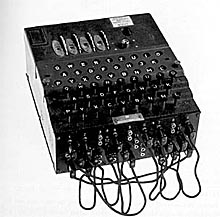
At the heart of the "Enigma" was a set of disks (or "rotors") able to rotate around a common shaft, each with 26 matching metal contacts circling the center, on the front and on the back of the disk. The contacts could be labeled A, B, C... Y, Z, one for each letter of the alphabet, and each was capable of making an electrical connection with whatever contact was facing it. The machine had a keyboard like a typewriter, and also a set of 26 lightbulbs.
When the operator pressed the key "K" (say), the source voltage was connected to the contact on the first disk corresponding to "K". The contact at the back of the disk would then connect the corresponding contact on the second disk, and from there the voltage would be passed to the contact on the third disk (a 4th disk was later installed too, to make the encoding even more secure).
In the back of the machine was a "plugboard" of scrambling wires, which fed back the signal through the same disk in some different place. If one pressed key K, for instance, the plugboard would return the current through the three disks in reverse order, reaching the contact of the letter "D", and the "D" lighbulb at that point would glow. (Pressing key K had automatically disconnected the "K" lightbulb, so it stayed dark).
At this stage, all this would produce would be a simple substitution code--"D" for "K", "Q" for "E" and so forth, depending on the setting of the plugs. Such codes are easily broken.
But there was much more: inside each of the disks, hidden from view, were wires that routed the power from each input contact to some other contact on the output side. So if "K" was pressed, the current may emerge from the "M" contact on the other side, the plugs might feed it back to "C" of the second disk, and it might be further scrambled by the wires inside that disk to "F", and so one. The third disk added another scrambling, so did the plugboard, and the connections were further scrambled on their way back--throught the 3rd, then 2n, then 1st disk, to a set of lamps labeled with letters A, B, C ,,, Z. An diagram of such scrambling is at the top of a long web article by Andy Carlson, which describes the machine and its history in much more detail than the brief overview given here.
So far, all this still produces a very elaborately hidden simple substitution code. What set the "Enigma" apart was that on the outside edge of each disk were 26 "teeth" or cogs, driven by a small extra gear like the cogwheels of a car's mile counter. If the wheels in a mile counter on a car engaged each other, they would rotate in opposite directions (besides problems of display). With an extra small gear engaging each pair of neighbors, they rotate in the same direction.
Each rotor had two gear wheels, on opposite faces: one face had a full set of 26 cogs, one for every letter, the other (which faced the preceding rotor) only one. It therefore took a full revolution of one disk to advance the next one by just one notch. In a mile meter, each full set of cogs has 10 teeth, so for each 10 miles, the counter of the "tens" advances one step. That wheel again has 10 cogs on its other side, turning (by means of a small connecting gear) a single cog on the "hundreds" dial, and do on.
In the "Enigma", each "rotor" had 26 cogs. Every time a letter was encoded, the first disk would advance one cog; every time the first disk completed a full turn, the next disk would advance one spot, and so on. Whatever the initial setting of the wheels was, it never (in practice) repeated itself
On the web you can find a Three Rotor Enigma Simulation in several languages, showing the intricate path of each encoding signal (the "Help" file there leads to further details). The arrows allow you to change the initial settings of the rotors, and you can drag reflector connections to new positions. Copy the encoded message, reset the rotors to the same initial positions and enter the encryption: the plain text then appears below.
The initial setting of the wheels (done by hand differently each day) was all important, for it decided all later settings in sequence. And the connections between key and lamp were symmetric: if on step 526 (say) key "A" connected to lamp "S", the two were connected by a complex electric path, and the same path would be traced in the opposite direction, too--key "S" would activate lamp "A". This way, when the encrypted message was typed on another Enigma machine at the receiving end with the same settings, the lights would spell out the hidden message and decode it.
This machine was invented in 1923 by Arthur Scherbius in Germany and was sold for encrypting business communications. The German army adopted it and modified it, but incredibly, Polish mathematicians (led by Marian Rajevski) developed a method for unscrambling its messages, helped by a German agent who provided some disks.
Just before the invasion of Poland by Germany in 1939, the Poles made their achievements available to France and Great Britain (including the "Bomba" sorting machine for decrypting the code, and reconstructed Enigma machines). The Germans kept modifying the code, and used it widely. In particular, one improved variant was used to communicate to submarines at sea, which around 1941 almost broke all shipping links to Britain. For instance, the code could direct subs to where supply convoys from Canada and the USA might pass, based on observations by submarines, airplanes and agents. If the allies could read such messages, ships could be diverted to different routes, and all the subs would find would be an empty sea, or perhaps a sub-hunting frigate.
The initial setting of the rotors was changed every day, so it was essential not just to break the code, but to do so quickly. A British team addressed the problem--headed by Alan Turing, a math genius, using the Polish methods, a supporting crew of experienced cryptologists, clever guesses and the (very rare) capture of disks from submarines. It just barely managed to keep ahead of the game, but it did decode many messages. At a certain point the Germans expanded the machine by providing a 4th disk, and more choices of disks. The US was by then in the war (and losing many ships to German submarines), but a large number of modified bigger "Bombas" installed in Washington managed to continue breaking the code
It is a fascinating story with many twists and turns, and interesting books exist about it. "Enigma: The Battle for the Code" by Hugh Sebag-Montefiore is highly recommended, though it can be technical in spots.
Note:
If you visit the area of Washington, DC, you might visit the free National Cryptology Museum maintained by the National Security Agency (NSA), about halfway between Washington and Baltimore. It is located east of the Washington Baltimore Parkway (Gladys Spellman Parkway) and is reached by taking the exit to Md. Rte. 32 East and then following the marked route to the museum (a former motel overlooking the parkway), through a parking lot and next to a parked transport plane.
Allow yourself plenty of time to view the many unique exhibits; NSA veterans sometimes serve as guides, and may have stories to tell. The catch is--it is only open on weekdays during working hours, or on the first and 3rd Saturday of the month. You will be able to operate an Enigma machine, view the "Bomba" and much more.
For a free copy of the booklet "Solving the Enigma: History of the Cryptanalytic Bombe" by Jennifer Wilcox, write to the Center for Cryptologic History. NSA, 9800 Savage Road, Suite 6886, Fort George G. Meade, MD 20755-6886, USA.
####################
|
|